The primary side of an ignition coil is basically just a simple coil with an iron core. During charging, the secondary side is open and can be ignored, so all that is left is a simple coil. It has an inductance like an ideal coil, however, unlike an ideal coil, it has resistance, capacitance, and the inductance changes with current.
Here are some notes on calculations for ideal coils: IdealizedCoilCalc.doc
Core's Affect on Inductance
Because the coil is using an iron core, there is a limit to the amount of magnetic flux the core can support. As the DC current in the coil increases, the effective inductance of the coil decreases. This means the charging characteristics of a real coil will not have the classic exponential shape of an ideal coil. It also means there may be a maximum current beyond which no further increase in current will produce an increase in stored energy. When that happens, the coil is considered magnetically saturated. Increasing the current or voltage beyond that point will show the coil to behave more like a resistor. In normal usage, a coil will not usually reach that condition, but will typically operate in a range where the inductance does steadily drop as the DC current is increased. That means incremental increases in primary current will not give the same incremental increases in stored energy as the overall current increases.
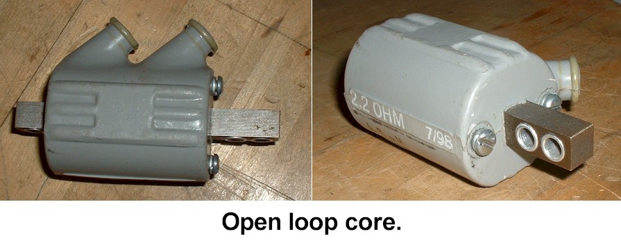
Many common ignition coils have a simple rectangular core that extends out beyond the edges of the coil windings. This is an "open-loop" core.
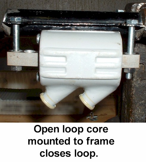
Some coils, mostly single-output coils, must be mounted to the frame in order to complete the electrical path for the high-tension circuit. Most dual-output coils do not use the frame to complete a circuit so don't have to be mounted for that reason, but should be mounted in order to ensure proper energy storage.
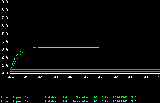
The following graph illustrates the difference in charging rate for a mounted, open-loop coil versus the same open-loop coil unmounted. Note the mounted coil charges at a slower rate, in terms of percentage of charge before saturation. But this does not mean it is slower in terms of the rate of energy stored. It may, in fact, be storing energy at the same rate as the unmounted coil, but because it can store more total energy, it takes longer to reach its maximum.
Affects of Heat and Resistance
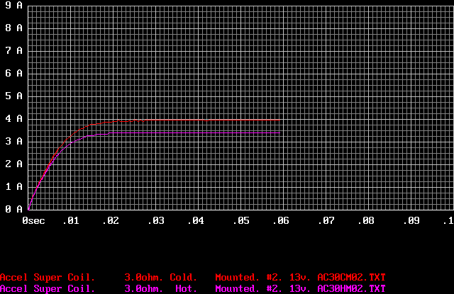
Because the coil is using a real conductor, usually copper, the DC resistance of the coil will not stay constant. The moment current starts to flow in the coil, the copper heats up and the resistance of the coil goes up. When a coil has a constant voltage on it, the resistance of the wire is what determines the final current in the coil. When this final current level is reached, the coil is said to have reached saturation. This is current saturation, not to be confused with the above-mentioned magnetic saturation. As the coil heats up, the saturation point reduces. This means the coil will not be able to store as much energy when it is hot, as when it is cold, given the same voltage applied.
Due to the nature of how a coil's resistance changes with heat, any measurement done with an ohm meter, to measure the resistance, should be done after the coil has been allowed to cool for at least an hour, in open air, if it's been heated. Likewise, if the resistance while hot is desired, it will have to be done using a voltage to current measurement while current is applied to the coil. This is because temperature is exponential. As soon as current is removed from the coil, the temperature drops rapidly then tapers off. The reading needs to be done while the current is flowing or the coil will be too cool to get an accurate resistance measurement while hot. Using current to measure the resistance while cold is also not practical. The moment any significant current flows in the coil, it starts to heat up. Cold resistance measurements should be done with minimal current, or a precision ohm meter. Hot resistance measurements should be done by measuring DC voltage and current in the coil.
The following graph illustrates how the same coil has a much lower saturation current when hot compared to when cold.
Part 2, DC and Steady State Specs
The coils were measured using a Fluke 73 III multimeter, an Amprobe AM-12 multimeter, and a Tenma 72-6634 inductance-capacitance-resistance (LCR) meter.
The inductance of each coil was measured cold on the Tenma LCR meter. The coils were measured first unmounted, then loosely mounted to a section of motorcycle frame using steel bolts.
The resistance of each coil was measured cold using the Amprobe meter.
Next coils had a small DC voltage applied while it's current was measured. The Fluke was used to measure the voltage on a 1-ohm, 25 watt, 1% resistor in series with the coil, and from that, the current was known. The Amprobe was used to simultaneously measure the voltage on the coil. From these two values, the resistance could be calculated. This is probably the most precise way to measure the DC resistance of the coil, but suffers from the accumulation of heat, so readings had to be taken quickly.
The resistance of each coil was also measured by the Fluke meter, both while cold, and while hot. Because, as was discussed earlier, the coil's temperature drops rapidly after removing the heating current from the coil, the measurements had to be taken quickly, but even a few moments showed significant reduction in resistance, so the hot readings may not be very accurate.
Cold readings were taken at room temperature. On the higher resistance coils, (above 1 ohm), hot readings were taken by applying current to the coil for about 10 minutes under a duty cycle of 60msec on, and 100 msec off. These coils got hot enough that the cores could not be touched for more than 3 seconds. The low resistance coils, (below 1 ohm), had a much shorter duty cycle of only a few msec. They did not get appreciably warm, so hot readings may not be accurate for those coils. Those particular coils also did not have any part of the core exposed. They were closed-core coils.
Equipment: Fluke 73 III. Amprobe AM-12. Tenma 72-6634 LCR. Dale 1ohm, 25W, 1% resistor. Home made 4~19v, 10Amp regulated power supply.
Mounting: Loosely mounted with bolts onto a piece of frame. Sometimes using steel spacers.
----Kaw KZ 650 points coil #1----
Open loop magnetic core.
Tenma Cold Unmounted: 11.25mH
Tenma Cold Mounted: 13.37mH 13~16mH depending on how it was mounted.
Fluke Cold: 4.0 ohm
Fluke Hot: 5.1 ohm
Amprobe Cold: 4.1 ohm
------------------------------
Using current through 1ohm, 25w, 1% resistor
(Fluke measures V on R, Amprobe measures V on coil).
Fluke: 0.770v = 0.770a
Amprobe: 3.06v
Calc ohms: 3.97 ohm
----------------------------
Open loop magnetic core.
Tenma Cold Unmounted: 11.65mH
Tenma Cold Mounted: 13.96mH 13~16mH depending on how it was mounted.
Fluke Cold: 4.0 ohm
Fluke Hot: 4.9 ohm
Amprobe Cold: 4.3 ohm
-------------------------
Using current through 1ohm, 25w, 1% resistor
(Fluke measures V on R, Amprobe measures V on coil).
Fluke: 0.763v = 0.763a
Amprobe: 3.11v
Calc ohms: 4.08 ohm
--------------------------
Open loop magnetic core.
Tenma Cold Unmounted: 13.13mH
Tenma Cold Mounted: 15.75mH 15~18mH depending on how it was mounted.
Fluke Cold: 3.2ohm
Fluke Hot: 3.8ohm
Amprobe Cold: 3.4ohm
------------------------
Using current through 1ohm, 25w, 1% resistor
(Fluke measures V on R, Amprobe measures V on coil).
Fluke: 0.925v = 0.925a
Amprobe: 2.95v
Calc ohms: 3.19ohm
------------------------
Open loop magnetic core.
Tenma Cold Unmounted: 13.09mH
Tenma Cold Mounted: 15.63mH 15~18mH depending on how it was mounted.
Fluke Cold: 3.1ohm
Fluke Hot: 3.6ohm
Amprobe Cold: 3.4ohm
----------------------
Using current through 1ohm, 25w, 1% resistor
(Fluke measures V on R, Amprobe measures V on coil).
Fluke: 0.943v = 0.943a
Amprobe: 2.93v
Calc ohms: 3.11ohm
-----------------------
Open loop magnetic core.
Tenma Cold Unmounted: 6.09mH
Tenma Cold Mounted: 7.39mH 7~8mH depending on how it was mounted.
Fluke Cold: 2.4ohm
Fluke Hot: 3.2ohm
Amprobe Cold: 2.6ohm
------------------------------
Using current through 1ohm, 25w, 1% resistor
(Fluke measures V on R, Amprobe measures V on coil).
Fluke: 1.121v = 1.121a
Amprobe: 2.75v
Calc ohms: 2.45ohm
---------------------------
Open loop magnetic core.
Tenma Cold Unmounted: 6.97mH
Tenma Cold Mounted: 8.19mH 8~9mH depending on how it was mounted.
Fluke Cold: 2.2ohm
Fluke Hot: 2.9ohm
Amprobe Cold: 2.4ohm
-----------------------
Using current through 1ohm, 25w, 1% resistor
(Fluke measures V on R, Amprobe measures V on coil).
Fluke: 1.195v = 1.195a
Amprobe: 2.68v
Calc ohms: 2.24ohm
---------------------------
This is and aftermarket one from an unknown manufacturer, presumably from China.
It is a 2-coil pack. Each coil has 2 posts.
It is used on 95-96 Dodge Neon, and other Chrysler vehicles from that era through early 2000's.
Wells model C940 ($75) is another aftermarket version of this coil.
Closed loop magnetic core.
Tenma Cold Unmounted: 4.98mH
Tenma Cold Mounted: 4.98mH
Fluke Cold: 0.6ohm
Fluke Hot: 0.7ohm (Was not warm to the touch after heating. Dwell was only 4.5ms.)
Amprobe Cold: 0.7ohm
----------------------------
Using current through 1ohm, 25w, 1% resistor
(Fluke measures V on R, Amprobe measures V on coil).
Fluke: 2.386v = 2.386a
Amprobe: 1.42v
Calc ohms: 0.60ohm
----------------------------------
This is and aftermarket one from an unknown manufacturer, presumably from China.
It is a 2-coil pack. Each coil has 2 posts.
It is used on 95-96 Dodge Neon, and other Chrysler vehicles from that era through early 2000's.
Wells model C940 ($75) is another aftermarket version of this coil.
Closed loop magnetic core.
Tenma Cold Unmounted: 5.03mH
Tenma Cold Mounted: 5.03mH
Fluke Cold: 0.6ohm
Fluke Hot: 0.7ohm
Amprobe Cold: 0.7ohm (Was not warm to the touch after heating. Dwell was only 4.5ms.)
--------------------------
Using current through 1ohm, 25w, 1% resistor
(Fluke measures V on R, Amprobe measures V on coil).
Fluke: 2.396v = 2.396a
Amprobe: 1.43v
Calc ohms: 0.60ohm
------------------------------
This is a coil available from Dynatek. $160/pair
Model DC11-1 (2 coils per kit) or DC11-2 (1 coil per kit)
These specs are from their literature: Polarity Sensitive see instructions!
Measurements Procedure SAE J973a (50pF load).
Inductance: 3.7mH
Resistance: 0.5 ohm
-------------------------
Closed loop magnetic core.
Tenma Cold Unmounted: 3.32mH
Tenma Cold Mounted: 3.34mH
Fluke Cold: 0.5ohm
Fluke Hot: 0.6ohm (Was not warm to the touch after heating. Dwell was only 3.3ms.)
Amprobe Cold: 0.7ohm
----------------------------
Using current through 1ohm, 25w, 1% resistor
(Fluke measures V on R, Amprobe measures V on coil).
Fluke: 2.468v = 2.468a
Amprobe: 1.36v
Calc ohms: 0.55ohm
-------------------------
This is a coil available from Dynatek. $160/pair
Model DC11-1 (2 coils per kit) or DC11-2 (1 coil per kit)
These specs are from their literature: Polarity Sensitive see instructions!
Measurements Procedure SAE J973a (50pF load).
Inductance: 3.7mH
Resistance: 0.5 ohm
---------------------------
Closed loop magnetic core.
Tenma Cold Unmounted: 3.34mH
Tenma Cold Mounted: 3.32mH
Fluke Cold: 0.5ohm
Fluke Hot: ohm (Was not warm to the touch after heating. Dwell was only 3.3ms.)
Amprobe Cold: 0.7ohm
--------------------------
Using current through 1ohm, 25w, 1% resistor
(Fluke measures V on R, Amprobe measures V on coil).
Fluke: 2.471v = 2.471a
Amprobe: 1.37v
Calc ohms: 0.55ohm
-------------------------
This is an aftermarket one is made by Wells Manufacturing Corp.,
Fond du Lac, WI 54935
Model C849 coil (Chevy Cavalier) $21.99
Used on most Chevy Cavaliers from early 1980's to 2005, along with many other GM vehicles.
Replacement for ValueCraft 55-1920
Replacement for AC-delco D555
These specs were measured directly on a Fluke 73 ohmmeter, and a Tenma 72-6634 LCR meter:
Inductance: 1.9mH
Resistance: 0.5 ohm
The following spec was calculated from earlier tests using the voltage over current method.
Resistance: 0.402 ohm
The following specs were calculated from earlier tests measuring current and time, and using the earlier resistance calculation.
Resistance: 0.402 ohm
Inductance: 2.8mH
This coil reaches 5.5 amps in 1.2 msec with 14 volts applied.
-------------------------
This is a coil available from Dynatek. $160/pair
Model DC1-2 (2 coils per kit) or DC1-3 (1 coil per kit)
These specs are from their literature. No testing was done on these coils.
Measurements Procedure SAE J973a (50pF load).
Inductance: 14mH
Resistance: 3 ohm
-------------------------
$7 Aftermarket coil for 2000 - 2002 Hyundai Accent
Closed loop magnetic core.
Tenma Cold Unmounted: 1.841mH
Tenma Cold: 1.3ohm
Fluke Cold: 1.0ohm
Amprobe Cold: 1.1ohm
-----------------------
Using current through 1 ohm, 25w, 1% resistor
(Fluke measures V on R, Amprobe measures V on coil).
Fluke: 2.268v = 2.268a
Amprobe: 1.947v
Calc ohms: 0.858 ohm
-----------------------
Warmed up.
Using current through 1 ohm, 25w, 1% resistor
(Fluke measures V on R, Amprobe measures V on coil).
Fluke: 2.499v = 2.499a
Amprobe: 2.53v
Calc ohms: 1.012 ohm
-----------------------
Using current through 150 ohm, 25w, 1% resistor
(Fluke measures V on R, Amprobe measures V on coil).
Fluke: 6.19v = 0.0413a
Amprobe: 0.035v
Calc ohms: 0.848 ohm
---------------------------
Because coils don't behave as ideal inductors, it is not easy to predict the behavior of the coil's primary side while charging, based on simple resistance and inductance measurements. A simple number cannot fully characterize the coil's behavior. In addition to the inductance varying with the current, the temperature, and how the coil is mounted will also play a role. One solution is to simply provide a current versus time graph for each coil, under normal operating conditions.
In order to accurately predict how a coil will charge, in order to provide it with the adequate/ideal dwell time, a simple graph of the current versus time can be used. The graph would illustrate the behavior from direct measurement, while a constant voltage is applied to the coil. The voltage selected is 13v, even though a typical electrical system will have closer to 14v on it. This choice is made because there is typically at least 1 volt lost in a typical igniter's output circuit. Often the voltage loss actually varies with current, but for the purpose of isolating variables in the graphs, a static 13v will be applied.
Coil Charging Apparatus
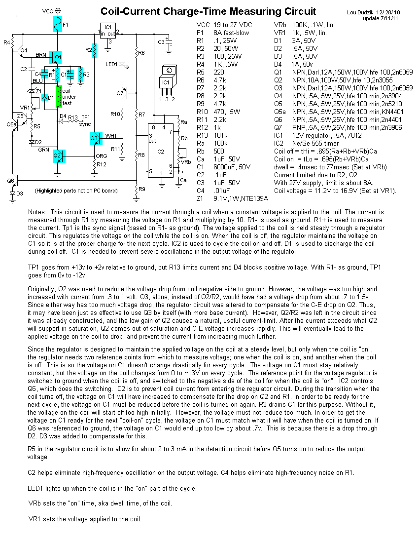
To measure the current in a coil when a voltage is applied, a circuit was devised to apply a constant voltage for a short time, then allow the coil to discharge fully through the primary side, rather than discharging through the secondary, as would normally happen. The circuit had an adjustment to control the dwell time, and an adjustment to control the applied voltage. The applied voltage was set to 13v for all tests. The circuit had a test point to allow for the measurement of current in the coil by measuring the voltage on a resistor in series with the coil. There is also a terminal in order to synchronize the data-capture device.
Data Capture Device
The coil-current data was captured by a microcontroller. The microcontroller received a synchronizing signal from the charging circuit when the coil was about to be charged. The microcontroller would then upload the data to a pc.
Graphing
The coil-current data is stored as a text file. A program then uses the text file to plot the current versus time relationship of each coil using a PC. The values were captured for hot and cold, and mounted and unmounted. The closed-core-loop coils only have unmounted readings taken. Since the desired data is that of the coils at operating temperature, and mounted normally, only the heated, mounted, graphs will be presented here.
The details of the
data-collecting hardware and software
are available below.
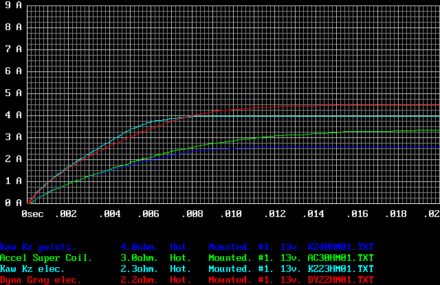
This first graph illustrates the current vs time relationship for the slower motorcycle coils. The coils are heated and mounted to simulate operating conditions.
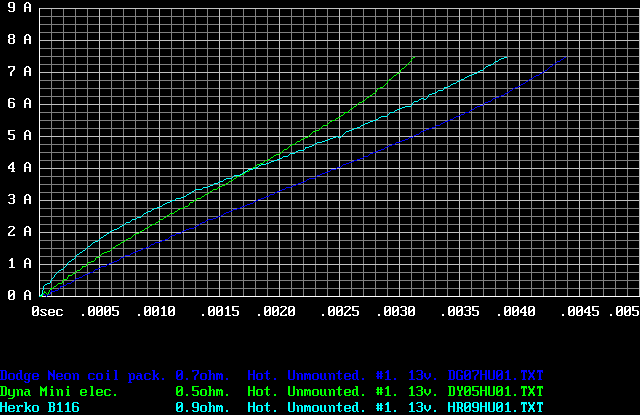
This second graph shows the current vs time relationship for the fast, Dyna mini-coils, the Dodge coil pack, and the aftermarket Hyundai Accent coil. The coils are heated to simulate operating conditions. These coils need not be mounted.
The raw data files are available below.
Data-Collecting Apparatus
Coil Circuit
A circuit was built to apply a regulated 13v to the coil. The circuit also discharged the coil. The circuit has adjustable dwell, and adjustable voltage, but 13v was always used for testing. Here are the details of the circuit:
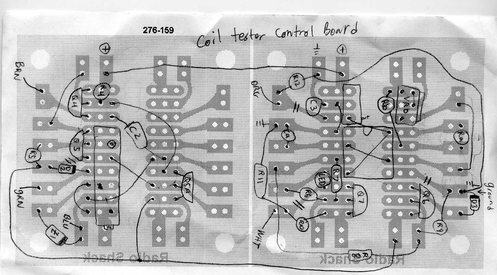
Here's the layout of the control board.
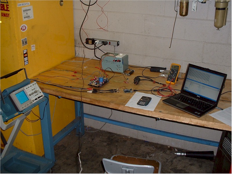
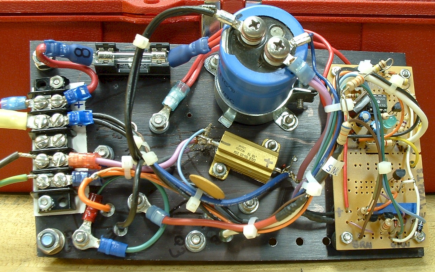
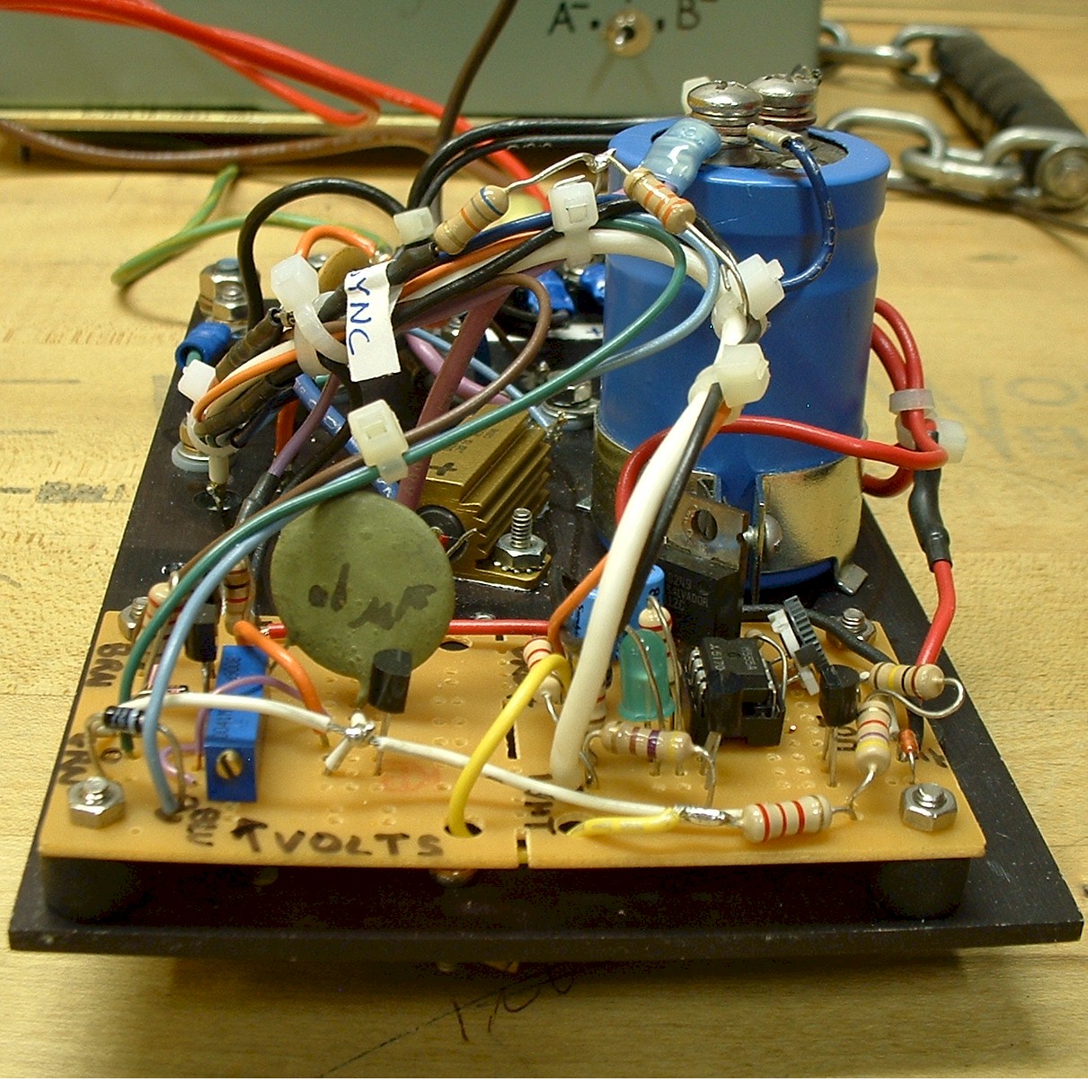
Here are photos of the assembled test circuit.
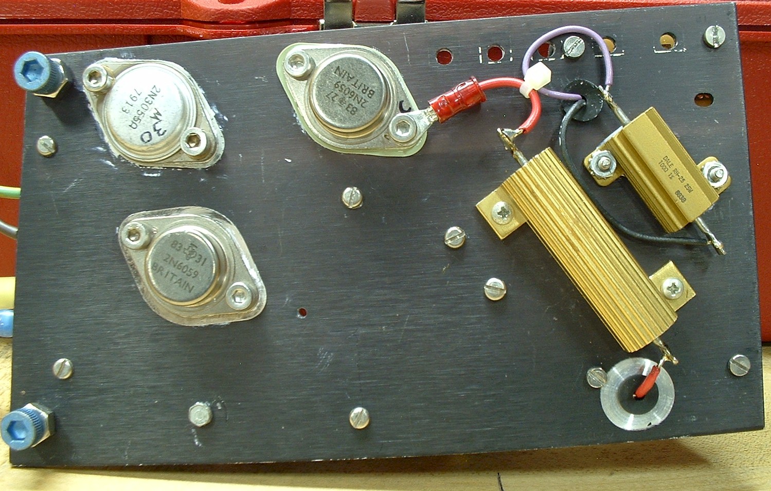
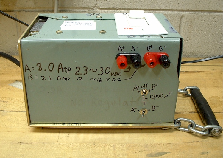
Power was derived from a filtered, but unregulated, variable DC supply.
Sampler
An Arduino UNO microcontroller kit was used to sample and transmit the voltage readings of R1 of the test circuit to a PC. Input A1 was used to sample the voltage of R1. The negative terminal of R1 was used as the ground reference. Input A5 was connected to TP1 of the test circuit to sychronize the data sampling of the Arduino to the test circuit. When a charge cycle would begin on the coil, TP1 would pull low. Input A5 had a pullup function enabled.
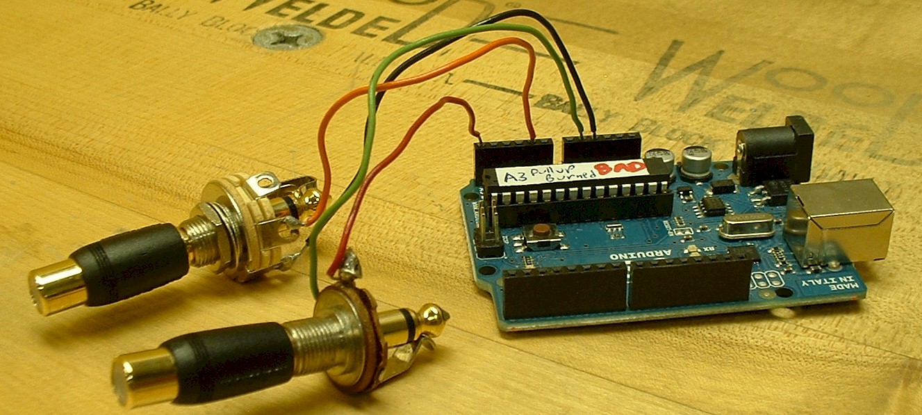
This is program being run by the Arduino: ArduinoCoilDataTextOutput.pde
Grapher
In order to store and graph the voltages sampled by the microcontroller, a PC was used. The microncontroller transmitted the data for one charge cycle through the USB port of the PC as a text stream. On the PC, the Hyperterminal application was used to capture the text streams and store them as text files. The text files could each contain one or more sets of data (charge cycles) for one coil. Then a Qbasic program was used to convert the data into a graph. In order to graph the data, the Qbasic program must be located in the same folder as the data files.
This is the Qbasic program used to graph the data : CoilDataGrapher.BAS
Data
The data is stored in text files for each test run for each coil.
Data Format
The name of the coil can be held in the text file. It is in the first line after "NAME".
The file name convention for each data file is:
2Char for make. (AC=Accel DG=Dodge DY=Dyna KZ=Kawasaki)
2Char for resistance in ohms. (Ohms, tenths of ohms)
1Char H or C for hot or cold coil temp.
1CHar M or U for mounted or unmounted core.
2Char for sequence number for when there is more than one type of the same coil.
The start of a sampling cycle is designated with an "$". The end with an "&". Notes can be written before $ or after & for any sample cycle.
The data is saved in time stamped voltage readings. So each point is a data pair. Each pair is listed as "t" followed by time in usec, then "," then "v" followed by voltage data as a coded value (0 to 1023), followed by a ",". There may be spaces interspersed along with carriage returns. Those will be ignored by the Qbasic program.
There can be multiple sets of data in one file. The program will display each one at a time and will prompt before each. After the last one is drawn, there will be a blank graph before starting over with the first set.
Data:
Download and save the data files to a new folder, then download the qbasic program and save it into the same folder and run the program. The PC will also have to have the Qbasic application installed in order to run the Qbasic program. That should be available on the internet.
KZ40CU01.TXT
KZ40CU02.TXT
KZ40HM01.TXT
KZ40HM02.TXT
KZ40HU01.TXT
KZ40HU02.TXT
AC30CM01.TXT
AC30CM02.TXT
AC30CU01.TXT
AC30CU02.TXT
AC30HM01.TXT
AC30HM02.TXT
AC30HU01.TXT
AC30HU02.TXT
DG07CU01.TXT
DG07CU02.TXT
DG07HU01.TXT
DG07HU02.TXT
DY05CU01.TXT
DY05CU02.TXT
DY05HU01.TXT
DY05HU02.TXT
DY22CM01.TXT
DY22CU01.TXT
DY22HM01.TXT
DY22HU01.TXT
HR09CU01.TXT
HR09HU01.TXT
KZ23CM01.TXT
KZ23CM01.TXT
KZ23CU01.TXT
KZ23HM01.TXT
KZ23HU01.TXT
KZ40CM01.TXT
KZ40CM02.TXT