Automotive Ignition Coil Tester
Lou D. 7/20/16 updated 8/10/16Introduction
This project is a circuit for testing automotive ignition coils. It is designed to create actual spark to confirm the coil's ability to produce high voltage. It can also confirm the coil's ability to perform reliably over time.
Parts List
              Parts List
        R1, R2, R3   1.5k ohm, 1/4 watt
        R4, R5, R6   220  ohm, 1/4 watt
            R8, R9   6.8k ohm, 1/4 watt
                R7   0.1  ohm,   5 watt, 1% tolerance
               VR1   10k  ohm, potentiometer, linear
               VR2   100k ohm, potentiometer, linear
        Cf, C1, Cs   1uF (1 micro-farad), 35 volt, electrolytic
            D1, D2   1N4004
                Q1   2N2907   .5a PNP, hfe>=100, TO-92 package
                Q2   2N2222(A) 1a NPN, hfe>=100, TO-92 package
               SW1   SPST toggle switch
                F1   10A, automotive fuse
               IC1   LM7805  5v regulator  TO-220 package
               IC2   NE555  timer   8-pin  DIP package
               IC3   FGP3440G2_F085  IGBT  TO-220 package


              Optional Parts
     R10, R11, R12   220  ohm, 1/4 watt
  LED1, LED2, LED3   3/16" standard green LED
                     3/16" LED grommet


              Other Parts:
                     Circuit board
                     Mini-blade fuse holder
                     8 pin DIP socket
                     TO-220 Heatsink


Ra = R1 + resistance of VR1
Rb = R2 + resistance of VR2
Dwell time = T-high = ~ .693 x Ra x C1
Rest  time = T-low  =   .693 x Rb x C1
Time is expressed in seconds.
Ra and Rb are expressed in ohms.
C1 is expressed in farads.
Circuit Overview
The timing control of the circuit is provided by a standard 555 timer (IC2) configured as a square-wave oscillator. The output of the oscillator can be broken down into two states, that when the output signal is high, and that when the output signal is low. The high and low times, together, determine the final frequency, or RPM being simulated. The dwell duration, which is the high-signal duration, is controlled by VR1. Spark occurs at the end of the dwell duration. The rest duration, which is the low-signal duration, is controlled by VR2. The rest duration is the main source of RPM control since it covers a wider range of time. However, at higher RPMs, when the rest duration is very short, the dwell duration will significantly affect the final RPM.The 555 timer output signal drives the IGBT module (IC3), which in turn controls the coil's primary signal. When the timer's output signal is high, the IGBT allows the primary current to flow. When the timer's output signal is low, the primary current is stopped. The spark happens when the primary current goes from flowing to stopped. The IGBT is needed to handle the high current flowing in the primary, but it also must be able to handle the moderately high voltage spike that is generated in the coil's primary winding when the primary current is stopping. The selected IGBT is specialized to handle these tasks.
With the dwell set to maximum, and rest set to maximum, the frequency is about 800 sparks per minute. With the dwell and rest set to minimum, the frequency is in the range of 26,000 sparks per minute.
The details of the operation of a standard 555 oscillator will not be covered as it is readily available on the net.
Setting Dwell
The range of dwell time, adjusted by VR1, is roughly 1 millisecond to about 10 milliseconds.For coils that measure in the range of about 3 to 5 ohms in the primary circuit, the dwell should be set to maximum. This should ensure adequate energy stored in the coil. But this will significantly limit the frequency of the sparks. When the frequency is maximized by the RPM control, higher frequency can be obtained by reducing the dwell. However, with the dwell reduced too much, the coil may no longer be able to produce reliable, 1/2", sparks. This should be avoided.
For coils that measure in the range of about 0.5 to 3 ohms, the dwell should be set somewhere in the first half of the range. Because there is a current limit circuit acting as a safety, there should be no harm in setting the dwell too long for the coil, as the current limiter will automatically end the dwell when the primary current reaches the limit.
Giving the coil a dwell period that is too short may give the appearance that the coil is bad. It is important to know what the dwell will be like on a given vehicle using a given coil. If the vehicle's dwell is not a good match for the coil, it may appear the coil is bad, when it is merely in the wrong application. If the coil appears to be good, on this test device, but does not seem to work well in a vehicle, make sure the vehicle's dwell is appropriate for the coil. When there is a problem with inadequate dwell, often, the coil's resistance is too high for what the vehicle was designed to use. Symptoms will include spark cutout at higher RPMs especially under heavier load.
Giving a coil a dwell period that is too long will usually produce a good spark, but the coil will get hot and will likely degrade over time, or may suddenly fail. It may also damage the points or igniter, if so equipped. This test device will not have this problem, but it is important to know a vehicle's dwell will be appropriate for a given coil to promote longevity.
6 Amp Current Limit
This project includes a current limit circuit. If the limit is reached in the primary circuit, the primary current will be stopped immediately, which yields a spark, and the 555 timer is reset to start the new rest period. There is no current-hold function in order to prevent excessive heat dissipation in the circuit (and the coil). The current limiter forces the dwell time to be shortened, overriding the dwell setting, thus it affects the frequency of the circuit accordingly.R7 is used to detect the current. It has a very low resistance, and all/most of the coil's primary current flows through it. As the current in the coil increases, the voltage on R7 increases. Q2 detects the voltage, and when it crosses a threshold, Q2 turns on. R5 is a safety to limit the current through the base of Q2. R9 and R5 produce a voltage divider to set the threshold voltage, on R7, at which Q2 will turn on.
As the current in Q2 increases, it turns on Q1. R3 is a safety to limit the base current in Q1. R8 and R3 produce a voltage divider to set the point at which Q2 will turn on Q1.
The current limit is approximately 6 amps. R8 can be changed to adjust the current limit more precisely. Decreasing the resistance of R8 will increase the current limit. R8 should be within the range of 1.5K ohms to about 100K ohms. This should yield an adjustable range of approximately 5.5 amps to about 6.5 amps, but other component tolerances may affect this range.
When Q1 turns on, it resets the 555 timer by very quickly recharging C1. R4 is a safety to limit the rate at which C1 charges during a current limiter event. When C1 is charged, the 555 timer's output goes from high to low, and the rest period starts.
Power Supply
This circuit is designed to be used with a 12 battery as a power supply. The battery should be at least the size of a typical scooter or motorcycle battery. The size of the battery will affect how long the circuit will operate correctly, so bigger is better, as long as the voltage is still nominally 12v. It should not be any higher than 15v.IC1 is a voltage regulator to power the control portion of the circuit. Cf is a filter to provide a steady voltage for the control circuit. These two parts make the circuit more stable. D2 is protection for IC1, and also prevents accidental reverse-hookup on the battery from damaging the circuit.
Power and Signal Indicators
R10 with LED1, R11 with LED2, and R12 with LED3 are optional parts. They are used to indicate power and output status.LED1 is to indicate the circuit is powerd on.
LED2 is on when the primary current is at rest. It turns on right as the spark occurs.
LED3 is on when the primary current is flowing. It turns off right as the spark occurs.
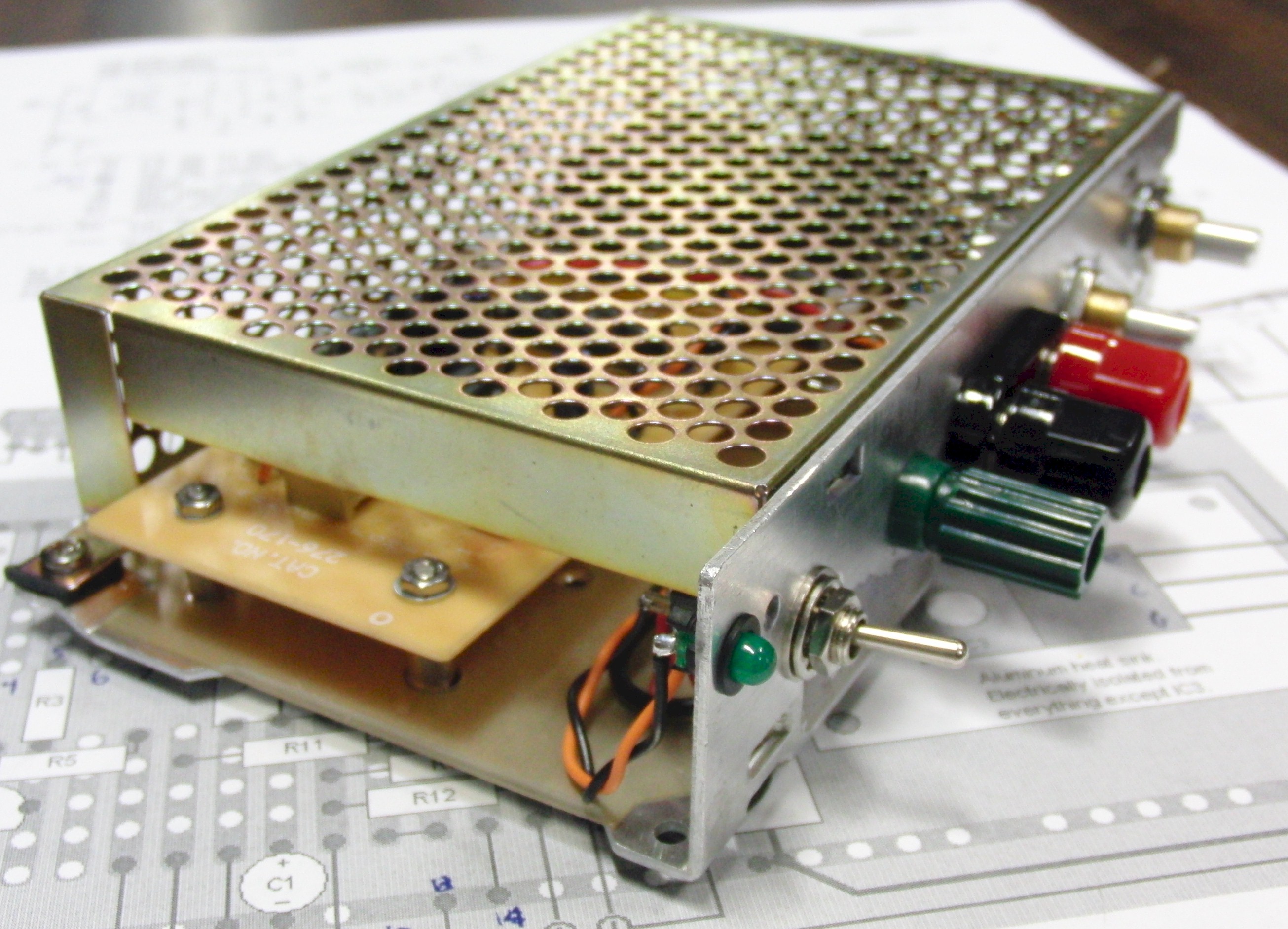
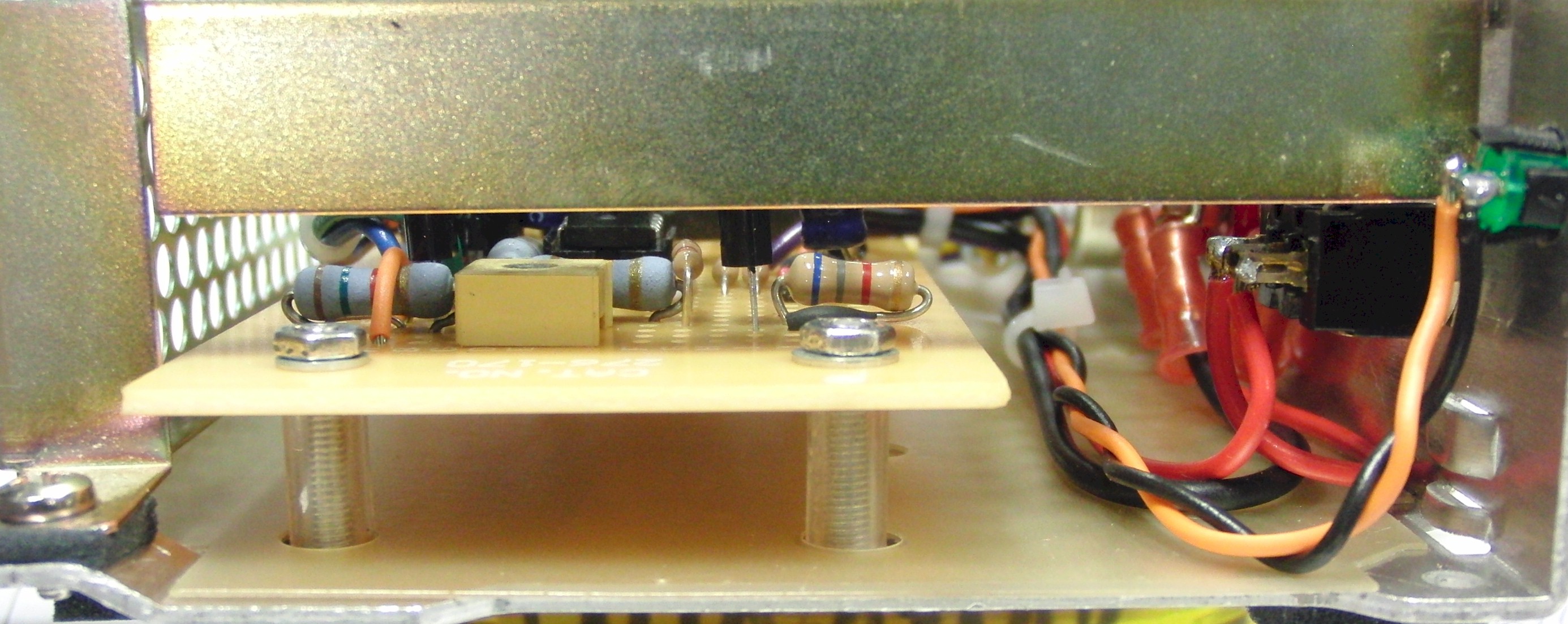
Construction
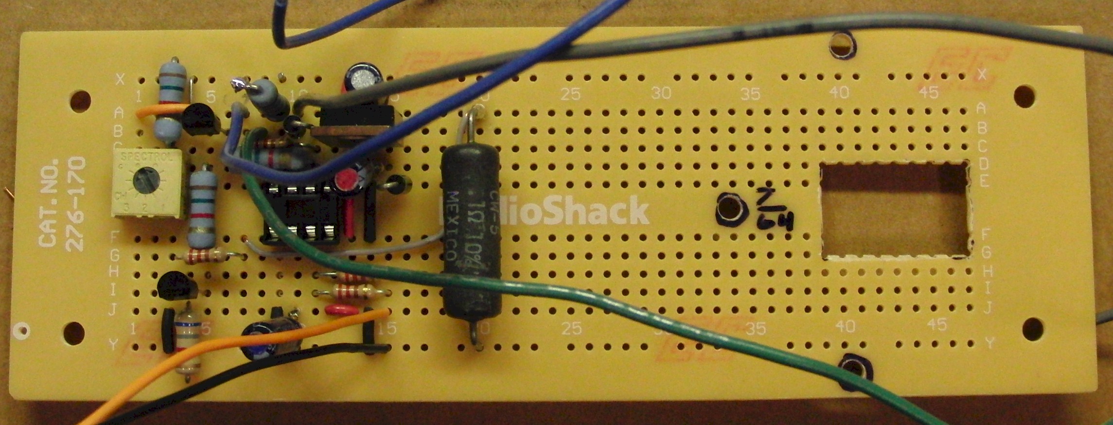
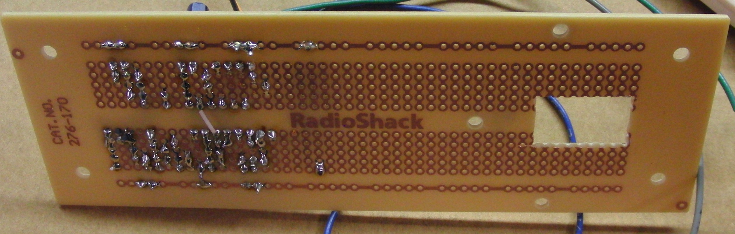
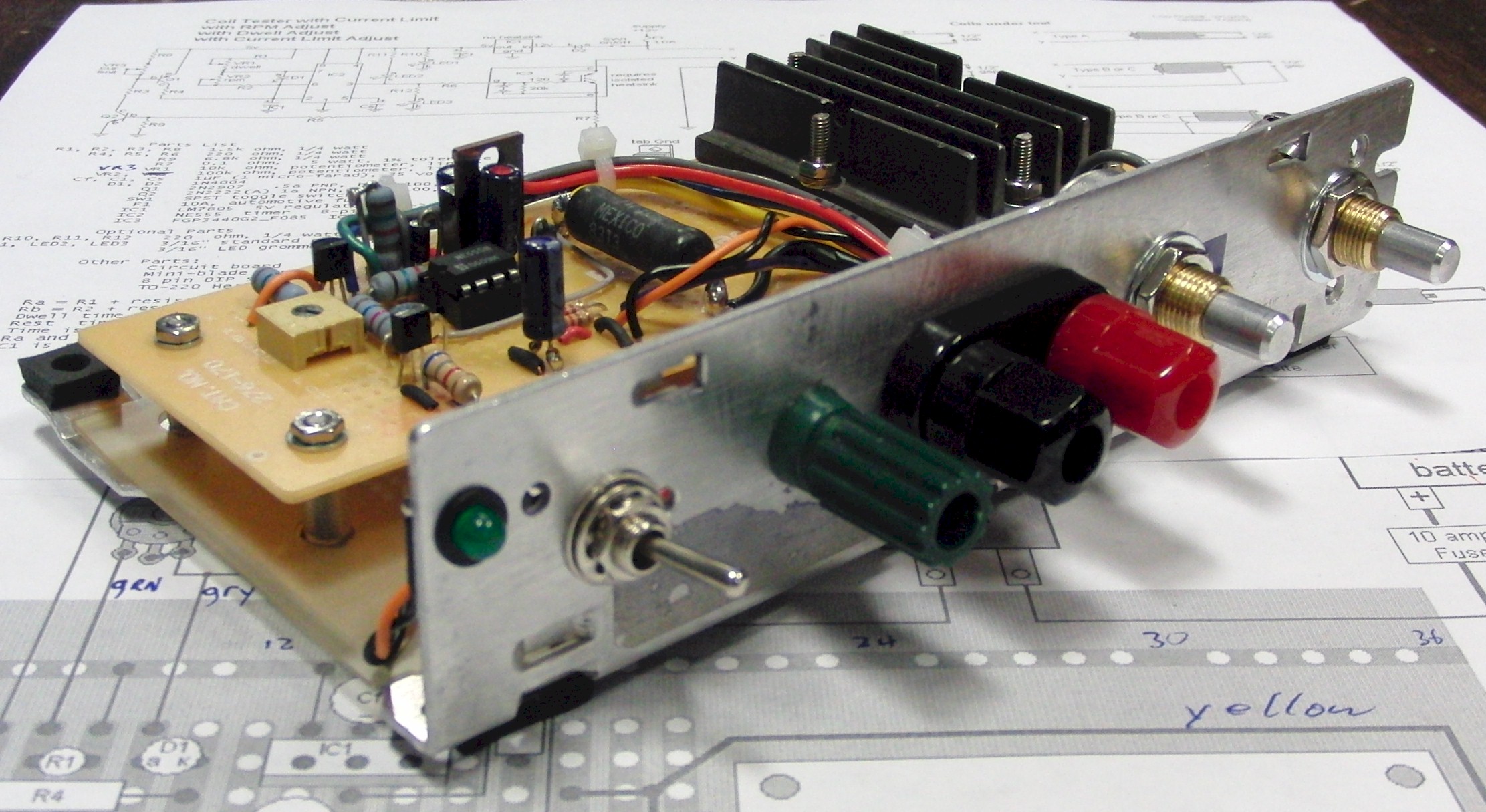
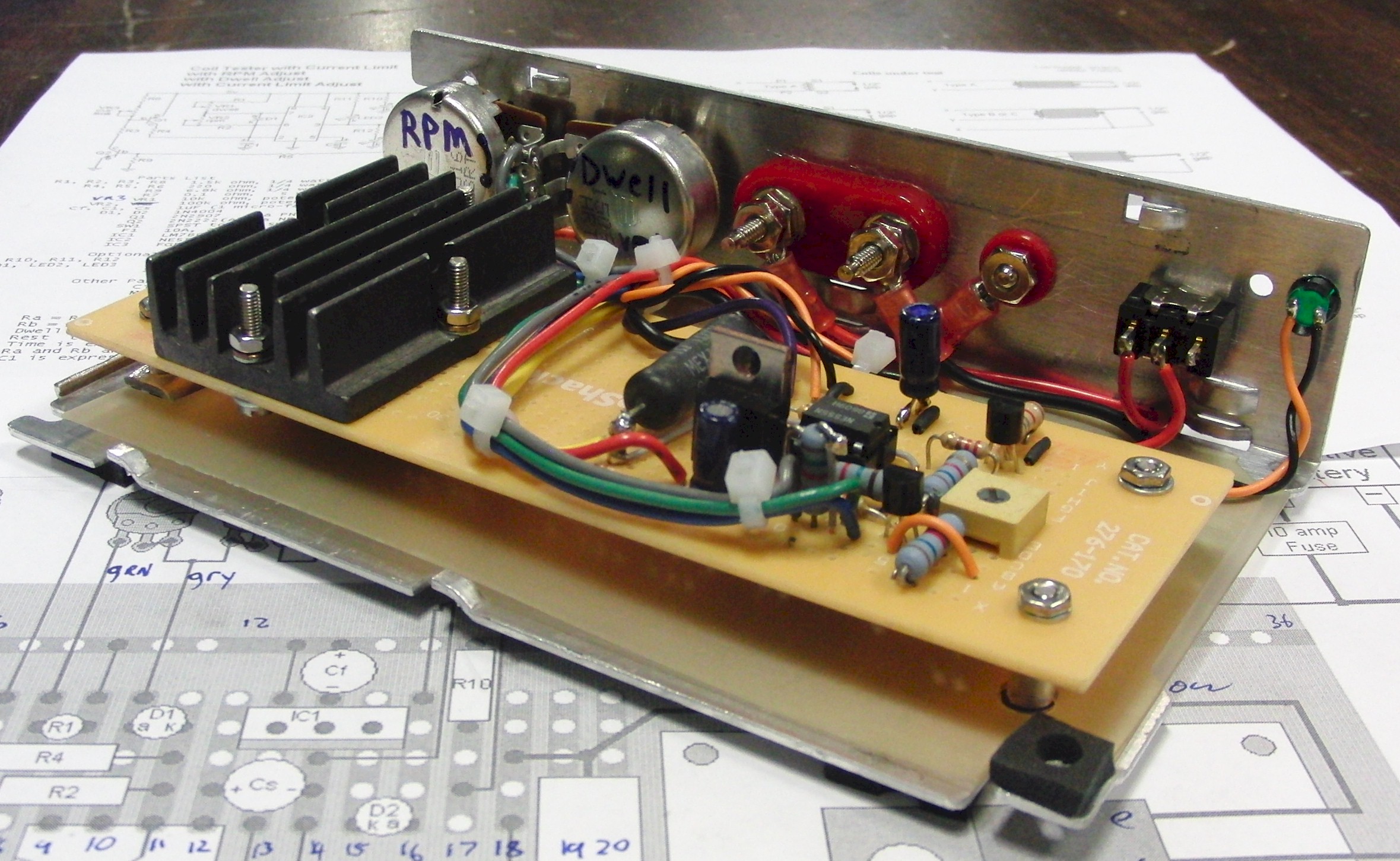
The IGBT device needs to be mounted on a heat sink. The size of the heatsink will depend on several factors related to the coil's impedance (resistance and inductive reactance) relative to the dwell duration and rest duration, and also how long the coils will be tested for. An 1/8" thick piece of aluminum, 1.5" by 2" rectangular, should suffice for brief tests on most coils. On longer tests, over a few minutes, it may get hot. Do not touch the heatsink or the IGBT while running. It will have spikes of several hundred volts on it!In this particular assembly, the IGBT is mounted to the bottom of the heatsink, inside a cutout in the circuit board, then wires were soldered directly to the legs of the IGBT. Two of the wires are heavier gauge (16 or 18 ga) to handle the full primary current. They are shown with a slightly heavier line on the pictorial view of the PC board.
Here are some photos of the circuit board and final assembly. Click on the photos to enlarge them. Use the back button to return here.
Note: These construction photos, below, are of a slightly earlier design which had a potentiometer in series with R8 to trim the current limit value. It was deemed unnecessary, and was eliminated. The selected resistance for R8 was changed accordingly.


Testing Different Coil Wiring Types
This coil tester will work on most ignition coils used on internal combustion engines. However, there are quite a few different coil wiring configurations to be aware of. Some of them require different hookups to the tester in order to work. The diagrams for the tester include a small pictorial of different coil types, and how they should be connected. Some of the coils can be connected multiple different ways. The way shown is usually the safest method in case the coil's internal wiring is unknown.Please note, the coil "type", as designated by different letters, is only for the purposes of this page and other pages on this site. The type designations do not represent any industry convention or official designation.
This page on Ignition types, and internal coil wiring for those types, has a lot more detail on how to determine the coil type, and may give insight to those who may want to investigate other ways to connect a particular coil.
Here is a video demonstrating the tester and early breadboard prototypes used during development.
Here is a video demonstrating the difference between a good coil and one with an intermittent failure. This one, as it turned out, had a bad connection at the plug wire inside the coil. As it heated up, it got worse.
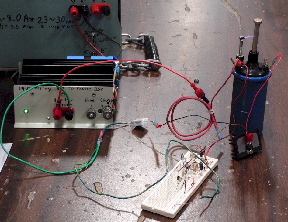
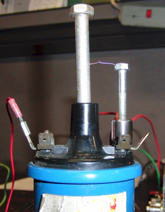
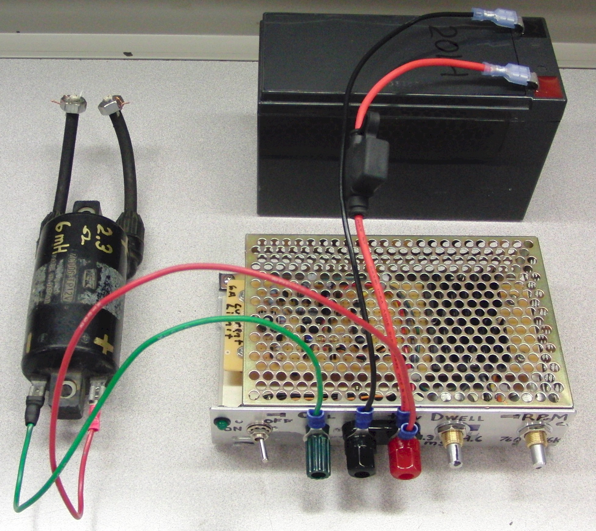
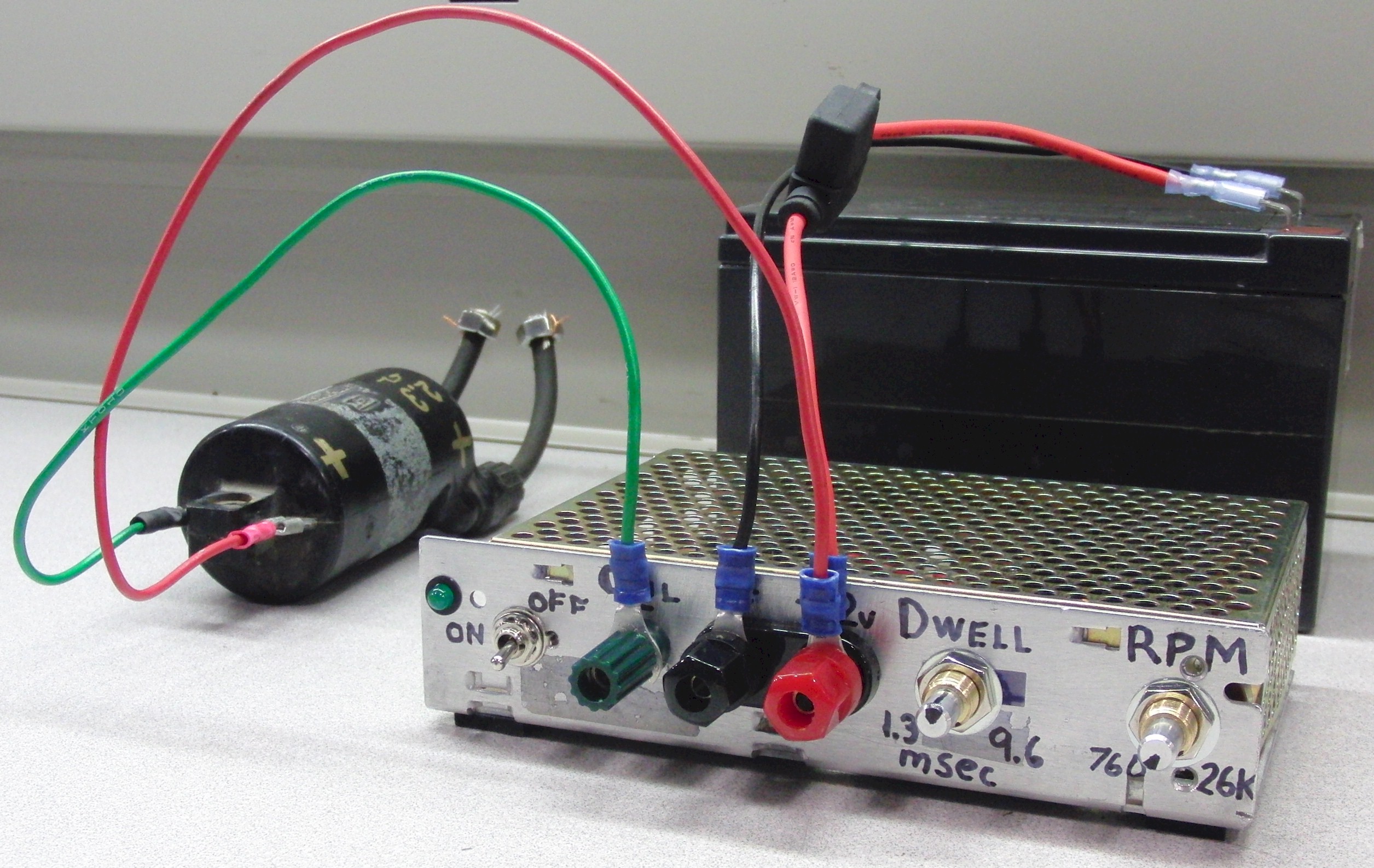
Here are some photos showing the circuit and a coil during development. The coil was from a Volvo P1800. It was 12v and had a 3-ohm primary winding. Notice, due to internal wiring, spark was tested to the positive primary terminal. It would have worked equally well to spark to the case of the coil, as long as the case was grounded by a strap (connected to the battery's negative terminal, as it would have been when installed in the car). A 12v power supply was being used in place of a battery, but the circuit should be used with a 12v automotive battery.
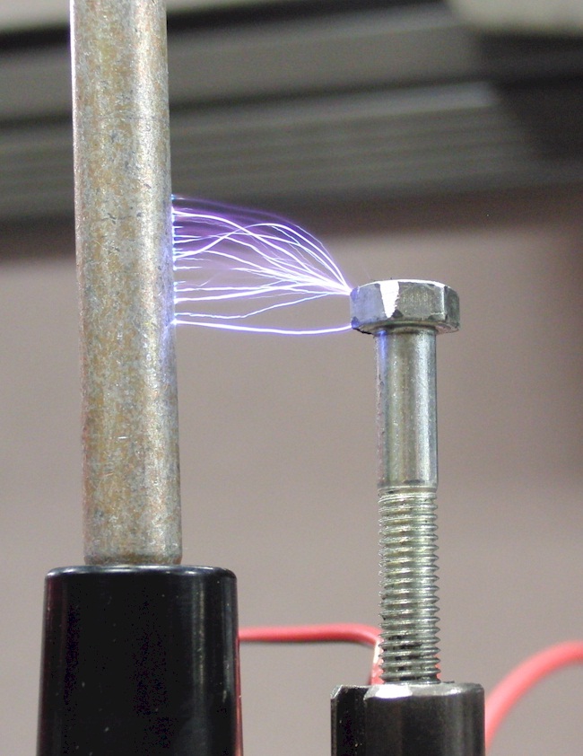
Here is a single spark, taken at a low RPM setting.
Here are multiple sparks, taken at a high RPM setting.