Most classic automotive ignition coils, whether the ignition is a Kettering type, capacitive-discharge, or magneto driven, are very similar to AC transformers. They typically have a 100:1 turn ratio. The primary side of the transformer is designed to operate at relatively low voltage and high current. The secondary side of the transformer is designed to operate at relatively high voltage and low current. The primary can be thought of as the input side, and the secondary can be thought of as the output.
The transformer is usually drawn this way:
The transformer can also be drawn other ways for convenience:
Primary : Input : Low voltage : High current
Secondary : Output : High voltage : Low current
Note the secondary side of the transformer, in the case of ignition coils, is drawn with more "loops", in the schematic, than the primary side. This is just to indicate which side is the high voltage side (which does actually have more windings).
It should also be noted that, here, "low voltage" covers a range of voltages, from that of the battery, which is usually 6v, 12v, or 24v, but also includes "moderately high voltage" spikes of up to 600v. "High voltage" is actually very high voltage, and in the range of tens of thousands of volts.
There are many different wiring configurations for such coils. They may have one or two primary terminals (or wires), and one or two secondary terminals (or wires). On some coils, the case, or core, or any mounting point, may be a connection, and may also be a junction for connections to both the primary and secondary side. This can lead to confusion on how to test such a coil, since the connections to the transformer will not be readily apparent, and may not be independent of each other.
This page will briefly discuss some of the more common types of ignitions, and how to determine the internal wiring of some of the different, common, coils.
Being like a transformer, the input and output have a polarity relationship to each other. For most applications, the polarity won't be important, but for testing, it may be relevant.
This page will also discuss how to determine the secondary (output) polarity relative to the primary (input) polarity.
Ignition Background
Automotive ignitions come in many types. The following descriptions are meant only as a brief summary so the reader can get an idea of what type of ignition he/she is dealing with. These descriptions are by no means complete.
Kettering Ignition
The most common type of automotive ignition is probably what is known as a Kettering ignition. This type uses a steady DC supply, through a set of points, or a transistor, to energize a flyback coil. A flyback coil generates a magnetic field when a current flows through its primary winding. This field stores energy. When the current is suddenly interrupted (by points opening), the field collapses, and the stored energy creates a moderately high voltage spike on the primary side of the coil. The condenser, which is just a capacitor, provides a slight delay in the creation of this spike, thus allowing the points to get open far enough to prevent the moderately high voltage from arcing across the points. The coil, acting as a transformer, then steps up this moderately high voltage spike to produce a very high voltage spike on the secondary winding. The secondary winding provides the very high voltage to the spark plug to cause a spark.
Here is one, simplified example of a Kettering Ignition:
CDI
Another, very common, type of ignition is abbreviated as CDI . This stands for capacitive-discharge-ignition. A CDI uses an ignition coil, which can be much like the one used in a Kettering ignition, but CDI differs from Kettering in that the spark energy is not stored in the coil. The spark energy is stored in a capacitor. This is done when the capacitor is very quickly charged up to several hundred volts, usually 300 to 600v. The power for charging the capacitor may come from a charging coil, near a rotating set of magnets on the crankshaft, producing moderately high voltage pulses. Alternatively, the power may be generated in a solid-state device producing several, moderately high voltage pulses. Each pulse raises the total voltage stored on the capacitor. This moderately high voltage, stored on the capacitor, is then suddenly discharged, usually through a silicon-controlled-rectifier (SCR, which is a type of thyristor), which causes a large spike of current to flow through the primary side of the coil. The coil, in this case, is simply used as a step-up transformer . The coil "steps up" the voltage to produce a very high voltage on the secondary winding. This very high voltage results in a spark at the spark plug.
Here are four, simplified examples of CDI systems:
The Magneto
Another type of ignition is called a magneto ignition. A magneto is simply a coil which generates a single, brief, precisely timed, pulse of AC current when a magnet passes by it. (The charging coil, seen above in the CDI ignition, can even be considered a magneto, although it actually produces several pulses.) The magneto can be thought of as the power generating portion of the magneto ignition. Ignitions using magnetos can be categorized into two different groups, described below.
Flyback Magneto Ignition (Integrated Magneto Coil and Ignition Coil)
Some magneto ignitions use a coil as a flyback coil. In this type, the ignition coil is integrated as part of the magneto. Normally, the pulse of current produced would be AC, but the current, in this ignition, is switched off by a set of (opening) points or a transistor, just as the current reaches a peak value. Thus, it's really a short DC pulse, which gets cutoff abruptly, similar to that in a Kettering ignition. The flyback effect produces the spark similarly to that in a Kettering ignition. This type of magneto is often found on lawn mowers where there is no battery.
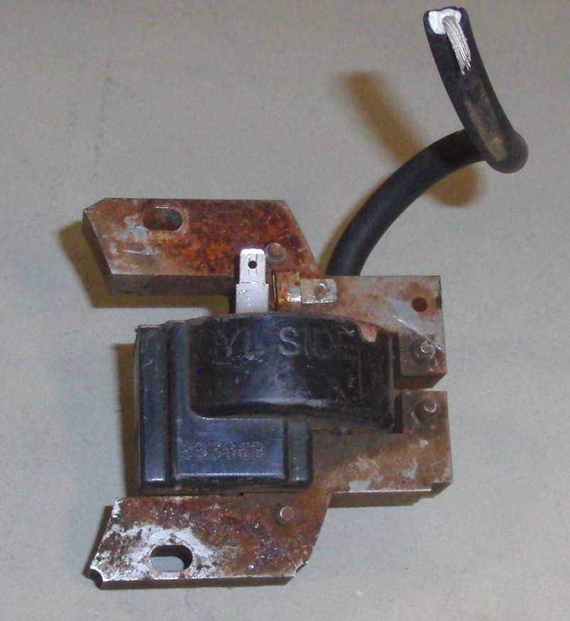
Integrated magneto/ignition coils are usually easy to identify by the curved portion of their core laminate. It is curved to match the curved flywheel/rotor containing the permanent magnet.
Here is an example of an integrated magneto/flyback ignition coil showing the curvature of the extended portion of the core:
Here is one, simplified example of a magneto system using an integrated, magneto/flyback ignition coil:
Stepped-Up Magneto Ignition (Discrete Magneto Coil and Ignition Coil)
Some magneto ignitions use the ignition coil only as a step-up transformer. In this type, another, separate coil is actually the magneto. This magneto coil is the one that has a permanent magnet passing by it, and generates a pulse of current. Like in the flyback type of magneto ignition, a set of (opening) points or a transistor, switch off the AC pulse at the right time, thus truncating the pulse into a brief DC pulse. This abrupt interruption of the current in the magneto coil has a flyback effect, producing a small pulse of several hundred volts on the magneto coil. However, the magneto coil does not step up the voltage to make a spark. Instead this pulse is fed to the ignition coil, much like how the CDI ignition operates, to step-up the voltage to produce very high voltage at the spark plug. This type of magneto ignition is often found on small motorbikes where the igniton can operate without a battery.
Here is one, simplified example of a magneto system using a discrete magneto coil and discrete, step-up ignition coil:
Note on spark voltage, for all of the above ignitions:
After the spike in primary and secondary voltage, when the spark begins to initiate, both primary and secondary voltages drop down to an intermediate voltage for the remaining duration of the spark discharge. This intermediate voltage may be in the range of about 1/10 of the initial spike, in open-air tests.
Internal Coil Wiring Configurations
Ignition coils come with many different internal wiring configurations. Each configuration is not necessarily used on only one type of ignition system. Some ignition systems can use multiple configurations, or one configuration may be used on multiple ignition types.
Note: The following configuration-type designations are only valid for the discussions on this web page, and related pages on this website. They are not an industry designation of any kind. Designations found elsewhere may be completely unrelated or contradictory.
Two-Primary / Two-Secondary ("Type A")
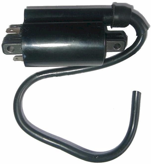
The type of coil that most resembles a transformer in terms of wiring, is the Kettering type designed to fire two spark plugs simultaneously. This type of coil has two input terminals (or wires) and two output terminals (or wires). Here is a typical example from a classic, inline-four motorcycle. The motorcycle would employ two of these coils to provide spark for four cylinders. This type of coil is easy to identify since it has obvious connections to two spark plugs, and two primary connections (or wires).
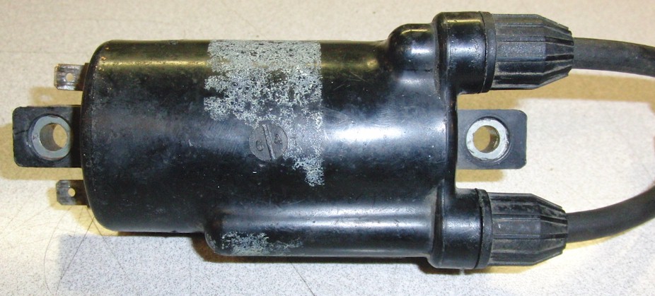
Type A :
P1 and P2 are primary connections. Both are terminals (or wires).
S1 and S2 are secondary connections. Both are terminals (or wires).
There should be no continuity from any primary connection to any secondary connection.
There should be no continuity from any connection to the case, core, or mounting points of the coil.
P1 to P2 will show continuity and will have very low resistance.
S1 to S2 will show continuity and will have very high resistance.
These coils are most often found on Kettering ignitions where a distributor is not used. Traditionally, due to the fact that points were a switched connection to ground, flyback coils, like this example, must have both primary connections isolated from ground, so they will always have two, independently accessible, primary terminals (or wires), neither of which will have an internal connection to the case, core, or mounting point of the coil. Likewise, since spark plugs are in contact with the engine, which is usually grounded, the spark plug connections on the coil must also be isolated from ground, and thus will not have an internal connection to the case, core, or mounting points of the coil. The secondary must also be isolated from the primary since a connection to the primary is, effectively, a virtual connection to ground. This is because the voltage on the secondary is so high that any voltage on the primary side will appear insignificant, and thus will appear as a direct connection to ground, (to the spark voltage).
These coils can also be used on CDI ignitions or even magneto ignitions, as long as the resistance values are appropriate. For use on those type of ignitions, either one of the primary connections would simply be permanently grounded, externally.
The connections for a Type A coil are easy to identify, and relatively self-explanatory.
P1 and P2 can be chosen somewhat arbitrarily. unless polarity is a concern.
S1 and S2 can be chosen somewhat arbitrarily, unless polarity is a concern.
See the discussion below for details on polarity.
Two-Primary / One-Secondary ("Type B" and "Type C")
Probably, the most common type of coil is that with a single output for the secondary. The ubiquitous, bottle-shaped coil, used on classic cars, is one of these. The bottle-shaped coil is usually used with a distributor to fire multiple cylinders.
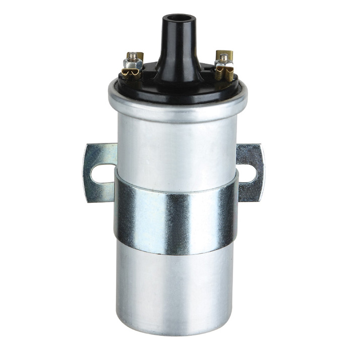
Let's define "Type B" to be the type with two primary terminals (or wires) and one secondary terminal (or wire), where the other secondary connection is the case, core, or mounting point.
Let's define "Type C" to be the type with two primary terminals (or wires) and one secondary terminal (or wire), where the other secondary connection is connected to a primary connection.
Type B :
P1 and P2 are primary connections. Both are terminals (or wires).
S1 and S2 are secondary connections. S1 is a terminal (or wire).
S2 is the case, core, or mounting point, of the coil itself.
There should be no continuity from any primary connection to the case, core, or mounting points of the coil.
There should be no continuity from any primary connection to any secondary connection.
P1 to P2 will show continuity and will have very low resistance.
S1 to S2 will show continuity and will have very high resistance.
Type C :
P1 and PS are primary connections. Both are terminals (or wires).
S1 and PS are secondary connections. Both are terminals (or wires).
The primary and secondary windings both share the PS terminal (or wire).
There should be no continuity from any connection to the case, core, or mounting points of the coil.
P1 to PS will show continuity and will have very low resistance.
S1 to PS will show continuity and will have very high resistance.
S1 to P1 will show continuity and will have virtually the same resistance as S1 to PS.
Because these are traditionally used on Kettering ignitions, like the Type A coils, these also must have both primary connections isolated from ground, so they will usually always have two, independently accessible, primary terminals (or wires), neither of which will have a direct connection to the core, or case, or mounting point of the coil. The difference, here, is that only one secondary terminal (or wire) will be used to create a spark. Ground is used to provide a path for the secondary current. The other secondary connection, then, must be grounded. In Type B, the secondary is directly grounded through the case, core, or mounting point of the coil, being in contact with a grounded part of the vehicle. In Type C, the PS terminal is seen by the secondary as a ground. This is because the secondary voltage is so high, any voltage on the primary, relatively speaking, will be insignificant, and thus, PS will appear as a virtual ground.
Like Type A coils, these coils can also be used on CDI ignitions or even magneto ignitions, as long as the resistance values are appropriate. For use on those type of ignitions, either one of the primary connections would simply be permanently grounded, externally.
A continuity test to the case, core, or mounting points, will show if the coil is Type B or Type C.
The connections for a Type B coil are easy to identify, and relatively self-explanatory.
P1 and P2 can be chosen somewhat arbitrarily. unless polarity is a concern.
See the discussion below for details on polarity.
Type C battery test:
The connections for a Type C coil are not easily identified with a continuity test. P1 and PS will appear electrically the same to an ohm meter. To identify P1 and PS correctly will require a small battery test with a volt meter. First confirm there is continuity between all three terminals. Then apply a AA battery to the primary terminals of the coil. The battery voltage will drop significantly, immediately, but should last long enough to complete the test. Connect the voltmeter as shown in the diagram, and measure the voltage on S1. The results of the S1 voltage will reveal which primary terminal is P1 and which is PS.
If the voltage on S1 is near 0v, then the positive of the battery is connected to P1.
If the voltage on S1 is closer to the battery voltage, which should be somewhere between 0.5v and 1.4v, then the positive of the battery is connected to PS.
The diagram also shows an "Alternative method". This should be used to confirm the findings in the first method.
One Primary / One Secondary ("Type D" and "Type E")
Coils designed specifically for CDI and magneto driven ignitions are very common, though they are more likely found on smaller motorcycles and scooters, and especially on lawn-care equipment. The notable difference, with regards to coil wiring, is that the primary side operates with one connection grounded. This means CDI/magneto-specific coils will only have one primary terminal (or wire).
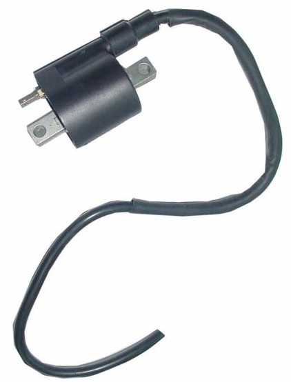
Let's define "Type D" to be the type with one primary terminal (or wire) and one secondary terminal (or wire), where the other primary connection, and other secondary connection, are the case, core, or mounting point.
Let's define "Type E" to be the type with one primary terminal (or wire) and one secondary terminal (or wire), where the other primary connection is the case, core, or mounting point, and the other secondary connection is connected to the first primary connection.
Type D :
P1 and PS are primary connections. P1 is a terminal (or wire).
S1 and PS are secondary connections. S1 is a terminal (or wire).
PS is the case, core, or mounting point, of the coil itself.
The primary and secondary windings both share PS
P1 to PS will show continuity and will have very low resistance.
S1 to PS will show continuity and will have very high resistance.
S1 to P1 will show continuity and will have virtually the same resistance as S1 to PS.
Type E :
PS and P1 are primary connections. PS is a terminal (or wire).
P1 is the case, core, or mounting point, of the coil itself.
PS and S1 are secondary connections. Both are terminals (or wires).
PS to P1 will show continuity and will have very low resistance.
S1 to PS will show continuity and will have very high resistance.
S1 to P1 will show continuity and will have virtually the same resistance as S1 to PS.
It should be pointed out that even though a CDI/magneto coil, normally, can't be used for a flyback ignition without making special provisions, a flyback coil can be used for CDI/magneto ignitions, provided the resistance and impedances are appropriate. It is just a matter of grounding one of the primary terminals of the flyback coil. However, this does not necessarily imply that flyback coils and CDI/magneto coils have the same electro-magnetic characteristics, even if their resistances and turn-ratios are the same. One general difference is the physical size. CDI/magneto coils tend to be smaller and lighter since they are not required to withstand long periods of active current flowing in their primary windings, as might occur in some Kettering ignitions.
Since some magneto ignitions, usually found in lawn mowers, integrate the magneto coil with the ignition coil, (as explained in the integrated magneto ignition description), it should be noted that even though the physical structure of that type of coil appears unique, the behavior of the coil is not very different from one with a more conventional appearance. As a matter of fact, that type of coil can be used with a CDI ignition, or with discreet magneto ignitions where the ignition coil and magneto coil are separate.
Here, again, is that example of this type of integrated, "lawn mower", coil.
If special provisions are made to insulate the frame or core of these types of coils, and it is deemed the electrical characteristics are appropriate, even these coils can be used in a conventional Kettering, ignition. They can also be bench tested this way by setting the dwell appropriately. Here is a photo of the lawn mower coil being tested using a transistorized Kettering ignition system.
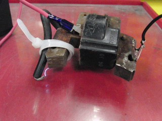
The spark jumps from the plug wire to the frame (lower left corner of the laminated frame in the photo). The wire is held near the frame with a ziptie just to control the gap, which is about 3/8" to 1/2". This tester uses a 12v supply and a very short dwell. That black wire with the alligator clip is not a permanent ground, it is the switched ground, controlled by the tester circuit, to produce the appropriate dwell. Details for the tester can be found elsewhere on this site.
Type D, Type E, battery test:
A continuity test cannot easily be used to determine if the coil is Type D or Type E. P1 to S1 will appear to have the same resistance as PS to S1. To identify the coil type will require a small battery test with a volt meter. First confirm there is continuity between all three terminals. Then apply a AA battery to the primary terminals of the coil. The positive battery connection is connected to the primary wire or terminal, and the negative battery connection is connected to the case, core, or mounting point, of the coil. The battery voltage will drop significantly, immediately, but should last long enough to complete the test. Connect the voltmeter as shown in the diagram, and measure the voltage on S1. The results of the S1 voltage will reveal if the coil is Type D or Type E.
If the voltage on S1 is near 0v, then the coil is Type D.
If the voltage on S1 is closer to the battery voltage, which should be somewhere between 0.5v and 1.4v, then the coil is Type E.
The diagram also shows an "Alternative method". This should be used to confirm the findings in the first method.
One Primary / Two Secondary ("Type F")
This is another possible configuration, designed specifically for CDI and magneto driven ignitions. However, this one is designed to be used with two spark plugs to be fired simultaneously.
Let's define "Type F" to be the type with one primary terminal (or wire) and two secondary terminals (or wires), where the other primary connection is the case, core, or mounting point.
Type F :
P1 and P2 are primary connections. P1 is a terminal (or wire).
P2 is the case, core, or mounting point, of the coil itself.
S1 and S2 are secondary connections. Both are terminals (or wires).
There should be no continuity from any primary connection to any secondary connection.
There should be no continuity from any secondary connection to the case, core, or mounting points of the coil.
P1 to P2 will show continuity and will have very low resistance.
S1 to S2 will show continuity and will have very high resistance.
Electrically, it is very similar to types D and E described above. The defining difference is that the secondary is completely isolated. Other than that, it can be tested similarly to the other CDI/magneto coils.
The connections for a Type F coil are easy to identify, and relatively self-explanatory.
S1 and S2 can be chosen somewhat arbitrarily, unless polarity is a concern.
See the discussion below for details on polarity.
Ignition Coil Polarity
The primary side of a transformer has a polarity relative to the secondary side. Looking at the ignition coil simply as an AC transformer, it too, has a polarity relationship between the primary and secondary windings. The internal wiring connections of the ignition coil were determined by the above discussions. It will now be shown how to determine the polarity relationship of those connections.
The polarity relationship can be defined different ways, but there is a traditional convention. The normal convention is; when an AC voltage, (of appropriate frequency), is applied at the input of the transformer, and the polarity of the output is chosen such that the positive portion of the input signal produces the positive portion of the output signal, and the negative portion of the input signal produces the negative portion of the output signal, the input terminals and output terminals are of the same polarity.
Because transformers are AC devices, their polarity is not usually labeled with + and -. Instead, a small circle or dot is used to indicate the terminals with matching polarity.
Note: because transformers are inductive devices, their input to output phase relationship is affected by frequency, particularly by low frequency. This can alter the apparent polarity if an AC signal is used and that signal is low enough in frequency to cause a phase shift between input and output. It is important to use test frequencies high enough so that phase shifting won't occur (by any significant amount), when using AC signals. A sinewave with frequency above 200 Hz or so should be adequate for most typical ignition coils.
Using Step Response to Determine Polarity
Applying a signal to the input of a transformer, and viewing the input-to-output relationship on a scope is a nice way to determine the polarity, but there is a simpler way for the specific application of ignition coils. That is to simply apply a DC voltage briefly to the input side of a coil, and view the voltage polarity, as measured by a voltmeter, on the output side.
When a DC voltage is suddenly applied to a circuit, the way the output of that circuit reacts to this voltage is called its "step response". If the step response voltage were to be viewed on a scope, it might look similar to this:
Notice, the input step is a positive DC voltage suddenly applied to the primary winding. The output "response", when the output polarity matches the input, has a large positive pulse, followed by a smaller negative pulse, followed by a smaller positive pulse, and so on. If the polarity of the output is reversed, the initial, large pulse, will be negative. When a DC voltmeter measures this response, the polarity of the largest pulse will determine the polarity registered by the meter. Because DC voltmeters measure average voltage, and the positive and negative pulses, in the decaying sinusoidal reponse, nearly cancel each other out, the DC voltage reading will be pretty low, possibly on the order of 0.1v to 1.0v or so (positive or negative). But because the initial pulse is the largest, that will determine if the meter registers a positive or negative voltage.
To determine the polarity, a AA battery can be used. Some coils have a direct connection between the primary and the secondary, so that should be used as ground, for simplicity. Connect the battery's negative post to ground. Then apply the battery so the positive can be connected to the other open primary connection. Connect a meter so the black lead is connected to ground, and the positive is connected to the open secondary connection. Set the meter to read about 1 to 10 volts max, and make sure the negative sign can be seen easily in case the result is negative. Right when the battery positive is connected, see if the meter registers a positive voltage or a negative voltage.
If the meter registers a positive voltage pulse, then the primary connected to the battery's positive post, and the secondary connected to the red meter lead, are of the same polarity.
If the meter registers a negative voltage pulse, then the primary connected to the battery's positive post, and the secondary connected to the black meter lead, are of the same polarity.
Note: opening the switch will have the opposite effect, so that can be used as an alternative method as well. In other words:
If closing the switch gives a positive voltage pulse on the meter for a given polarity relationship, opening the switch should give a negative voltage pulse, (confirming the polarity relationship).
If closing the switch gives a negative voltage pulse on the meter for a given polarity relationship, opening the switch should give a positive voltage pulse, (confirming the polarity relationship).
As noted in the diagram, the results are the same regardless of the switch position, as long as the battery polarity does not change. This means, in a Kettering ignition, the polarity seen on the meter when the test switch opens, is the same polarity that will be seen when the coil is in operation when the points open, or the transistor cuts the primary current, (as long as the vehicle battery is applied to the coil with the same polarity as the AA battery in the test).
Also note: there may be a small DC voltage registering on the meter if the battery is left connected. It can be positive or negative, depending on the wiring configuration, and may indicate some dirt is on, or in, the coil causing a small amount of continuity. Shorted windings in the coil could also cause this, but the coil would likely have other symptoms if this was the problem. This voltage should be small enough to be ignored. This should not affect the test because this value should be much smaller than the pulses created during the test. Thus the test will show correct positive or negative voltage readings, and will still be valid.
Primary / Secondary Current and Superposition
Among the different configurations for the coil wiring, there are four cases where the primary current and the secondary current actually flow through the same conductor. And in two of those cases, the secondary current actually flows through the primary winding. In some cases, due to coil polarity, the secondary current, or secondary voltage, oppose those of the primary, and in some cases they enhance it.
With that in mind, it raises the question of how does this affect the spark. It is beyond the scope of this page to detail the concept of "superposition", but the Superposition Theorem does explain how two simultaneous currents in a single conductor can be resolved to a single current, or two voltages across a single resistance can be resolved to a single voltage. But that may not necessarily predict how significant the effect will be in practical terms.
In order to investigate the effect, the four different circuits were built, all using the same parts. The coil (Dodge Neon coil-pack) was a dual output, low resistance coil, which could be wired in each of the four different configurations.
Results
There was no difference, in the sparks, which could be detected. Using 5/8", and later 3/4", gaps, the brightness and loudness of the sparks seemed apparently the same. When measuring the voltage on the primary side, using an oscilloscope, the estimated, average discharge voltage, and average discharge duration, was the same for each configuration. The measurements were not extremely precise, as sparks are generally somewhat erratic by nature, but in observing the duration and voltage, none of the four configurations showed any observable difference from any of the others. That is not to say that there is no difference, but that the difference could not be detected. A difference would be expected. A more precise experiment may be required to detect it.
(The diagrams are shown using points for illustration purposes only. The actual test igniter was an IGBT device.)
With a 5/8" gap, spark duration was about 973 usec, and primary discharge voltage was about 37.8v.
With a 3/4" gap, spark duration was about 780 usec, and primary discharge voltage was about 45.0v.
The primary discharge voltage is the approximate, average voltage on the primary winding, after the initiation of spark, during the remainder of the spark. The primary voltage just before the spark initiates will be several hundreds of volts.
For reference, this is a very rough sketch of the primary signal for all four configurations, with a 5/8" spark gap.
These results are almost anecdotal since they are only for one set of conditions on one specific coil type. But it does show, at the very least, for one instance, the different configurations have negligible difference on spark voltage and duration.
It should be noted, however, that polarity, at the spark plug itself may show some differences in actual use on a vehicle. This is because, in use, the temperature difference between the center electrode, versus the ground electrode, may result in less resistance to arcing if the polarity is set so the center electrode (hotter) emits electrons. With regards to the polarity determination test, seen above, this means the polarity of the spark plug wire should be such that it gets a negative pulse when the primary current is cut.