1 LED Voltage Monitor
adjustable for 6-volt and 12-volt
automotive systems
Introduction:
This project is a voltage monitor for the charging system on typical motor vehicles employing a 6-volt or 12-volt electrical system. It uses a single LED as an indicator.When the voltage is below the set threshold, the LED is off, and when the voltage is above the set threshold, the LED is on. The threshold is adjustable from about 6.5 volts to 16 volts. The voltage being detected is averaged, therefore this monitor does not detect peak-voltage. It is weighted to average the voltage for most automotive charging systems employing a single-phase or 3-phase alternator or generator. These systems must have a battery or capacitor in place to smooth out the pulses from the charging system in order to prevent the instantaneous voltage from going to zero. These systems also usually employ a rectifier. (A generator may produce DC by itself.) This monitor will not work accurately on systems that go to zero volts, such as in magneto-driven ignitions or AC lighting systems.
Circuit Overview:
This circuit can be connected to a vehicle’s electrical system at any point that has full battery voltage present.The vehicle’s system-voltage is scaled down through an adjustable voltage divider. This voltage is then averaged by a capacitor. Next, a comparator compares the voltage against a constant reference-voltage. When the voltage is higher than the reference-voltage, the LED is turned on. When the voltage is lower than the reference-voltage, the LED is turned off. When the voltage is equal to the reference-voltage, the average voltage of the system is at the threshold-voltage.
The user does not directly set the threshold-voltage. The threshold-voltage is the average value of the system-voltage at which the LED turns on. It is set indirectly by adjusting the voltage divider, which scales down the voltage so it can be compared to the reference-voltage, which is approximately 5.1 volts. The threshold-voltage should not be confused with the reference-voltage. The reference-voltage is always approximately 5.1 volts. The threshold- voltage is the average system-voltage at which the output of the divider circuit is at 5.1 volts. The threshold-voltage is also the average system-voltage at which the LED is turned on.
To set the threshold of the monitor prior to use, the user connects the monitor to a voltage equal to the threshold and adjusts the trimmer pot until the LED just turns on. A good way to set the threshold would be to simply connect it to the vehicle in question along with a voltmeter, then rev the engine until the desired voltage appears on the meter and turn the trimmer until the LED just turns on.
Circuit Details:
Please refer to the circuit diagram.Voltage divider:
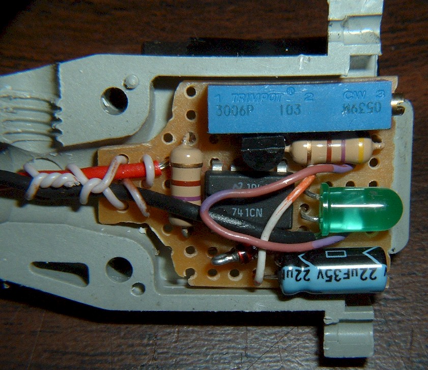
VR1 is a 10K-ohm trimmer pot. It acts as a voltage divider to reduce the system-voltage by a fixed percentage for comparison to a reference. Reducing the voltage through a large value resistor allows for easy averaging of the voltage as well. It will not handle much current so power is not a concern for VR1.Averaging Function:
C1 averages the voltage from VR1. It is selected as a 22uF, 25V, electrolytic capacitor. Because there is very little current flowing to IC1, C1 does not have to be very large. This averaged voltage is applied to the comparator (pin 3 of IC1).Comparator:
The comparator (IC1) is a uA741 op-amp integrated into a single chip. Most similar op-amps will suffice as a substitute. When the voltage at the + terminal of the comparator is higher than the voltage at the – terminal, the output of the comparator (pin 6) is high. When the voltage at the + is lower, the output is low.One note should be made on the behavior of the comparator. If the instantaneous system-voltage drops so low as to cause IC1 to turn off, the input to the comparator tends to drain the capacitor C1 briefly. Because of this, low instantaneous system-voltage can cause the monitor to be inaccurate. This is why this monitor requires a battery or capacitor to be used on the vehicle’s electrical system to prevent the voltage from dropping below 4V or so.
Reference:
The – terminal of the comparator is connected to a constant reference-voltage. The reference-voltage is supplied through R1 and is regulated by Z1. Z1 receives additional current through R3 and Q2 when the system-voltage is above 6 volts.R1 and R2 act as current limiters for Z1 and are selected as 470-ohm, 1/2W resistors.
For usage on 6-volt systems exclusively, R1 and R2 would be better selected as 180-ohm, 1/2W resistors.Z1 is a 5.1V, 1W Zener diode. It requires about 5mA to produce a reasonably steady 5V reference-voltage. It requires about 10mA to produce a very steady 5.1V reference. At low system-voltages (close to 6 volts), the current to Z1 is fairly low so the extra current from R3 is important. If this monitor will only be used on 12-volt systems, R3 and Q2 can be eliminated. In that case, Pin 7 of IC1 would be connected directly to the system-voltage input.
The current through Z1 to ground must be above 5mA to produce a reasonably steady reference-voltage. When the system-voltage is at 6.5V, R1 (R1 and R3 selected as 470 ohms) provides about 3.2mA and Q2/R3 provide about 1.7mA. Together, they provide Z1 with about 4.9mA. That is just enough to produce a reasonably steady reference of about 5.0V. If R1 and R3 are 180 ohms, they provide Z1 with about 12 mA.
Low-Voltage Cutoff:
R3 and Q2 are used to make sure the LED stays off when the instantaneous system-voltage drops very low. When the system-voltage drops below the 5V reference-voltage, the actual reference-voltage also drops accordingly. Meanwhile, the averaged voltage on C1 remains higher due to C1’s capacitance. This presents a problem. While the averaged voltage on C1 may be below the normal reference of 5.1V, the reference has actually dropped due to the instantaneous system-voltage being too low. This means the LED will be on when, in fact, it should be off. To remedy this problem, Q2 will cutoff the power to IC1 when the system-voltage drops below approximately 6V, thus keeping the LED off.It may appear, at first, that a remedy could be devised by using a capacitor to store the reference voltage. That is not satisfactory, however, because that would also delay the recovery of the reference voltage.
If the monitor is to be used exclusively on 12-volt systems, then R3 and Q2 are not needed and can be eliminated (as mentioned above). In that case, Pin 7 of IC1 would be connected directly to the system-voltage input.
LED driver:
Transistor Q1 is used to drive the LED. The comparator can drive the LED somewhat, but there are a few problems with that method. First, the low output of the comparator can sometimes be high enough to cause the LED to light up very dimly even when it should be off. The other problem is that the comparator is not capable of driving the LED very brightly. As its output current increases, its output voltage decreases. In addition, the above-mentioned function of Q2 would not be able to be implemented the same way.Q1 solves these problems. Notice that Q1 is used as a switch, but not in the conventional way. Q1 does not saturate, and the load is connected to the emitter instead of the collector. This arrangement allows R2 to act as the current-limit for the base circuit as well as the collector circuit. Since Q1 is in its active region, the collector-current must be approximately 100 times the base-current. This causes the base-voltage to increase and thus the comparator’s output current is reduced. This eliminates the need for a dedicated base-current limiting resistor. This arrangement works because the output voltage of the comparator is almost as high as the voltage applied to Q1’s collector. If the output of the comparator were significantly lower, the emitter-voltage of Q1 would have been too low.
R2 was chosen as a 470-ohm, 1/2W resistor. This ensures about 10 to 20mA in the LED when it’s on. If the monitor will only be used on 6-volt systems, a 180-ohm, 1/2W resistor can be substituted to get more brightness out of the LED.
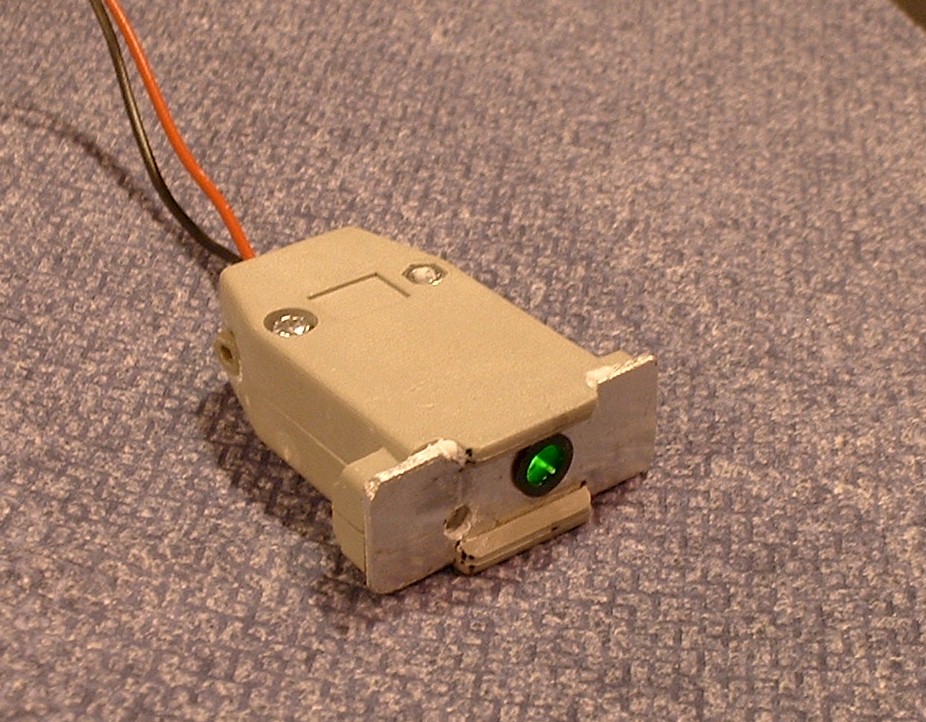
The LED is a standard 3/16” green LED.
Performance Results:
This circuit was tested with R1-R3 selected as 470-ohms. An oscilloscope was used to determine when the LED was starting to turn on, and when it was fully on. This was done by measuring the voltage on R2 and observing the duty cycle.The applied test signal was a 3v P-P triangle signal with adjustable DC offset and adjustable frequency. The average voltage was measured on a Fluke 73 multi-meter.
With the detector threshold set to 14.00 volts and using a 22uF capacitor as C1 , the circuit was tested at three different frequencies with the following results:
500 Hz:
LED starts to turn on at 13.96v
LED is fully on by 14.02v50 Hz:
LED starts to turn on at 13.92v
LED is fully on by 14.08v20 Hz:
LED starts to turn on at 13.83v
LED is fully on by 14.17v
With the detector threshold set to 14.00 volts and using a 44uF capacitor as C1 , the circuit was tested at three different frequencies with the following results:500 Hz:
LED starts to turn on at 13.96v
LED is fully on by 14.02v50 Hz:
LED starts to turn on at 13.96v
LED is fully on by 14.05v20 Hz:
LED starts to turn on at 13.90v
LED is fully on by 14.09v