The Dynojet needle only has one taper, and it starts later than the factory needles. This means the Dynojet needle will actually be leaner at very small throttle openings. The factory needles have a very short, slight taper, initially, then a longer, steeper taper after that. Here's a diagram showing the three needles' dimensions.
Defective Needles
Unfortunately, there are some non-marked needles that can be found in some no-name rebuild kits, which are essentially defective. The kits are simply labeled KK049, and come in plain plastic bags inside white cardboard boxes. KK049 is the number of the Keyster rebuild kits, which are of high quality and have proper needles. These no-name kits are trying to imitate the Keyster kits.
The non-marked needles are too skinny overall. They are similar to the 4D93/Y77 needle, but have no markings. It would take a very accurate micrometer to identify the needles since the differences in the diameter are usually less than .001" at any given position along the needle. In fact, the clip portion of the needle is skinny enough to press fit into the needle jet. This should not be possible with the 4D92 or 4D93 needle. The factory needles cannot do this. The difference is only .0002" which prevents this.
Along most of the needle, this difference can be tolerated, and compensated for, but near the top, where the off-idle portion of the throttle operates, the difference is dramatically too rich. The non-marked needle, in the middle of the operational range, is the equivalent of approximately 1.6 clip positions. This makes the non-marked needle, even at the leanest clip position, richer than a stock needle. But the real problem is that it is excessively rich in the critical area between 1/16th and 1/4 throttle. The bike may run, and be functional, but will be very rich. This will not be good for fuel comsumption and may lead to plugs carbon-fouling.
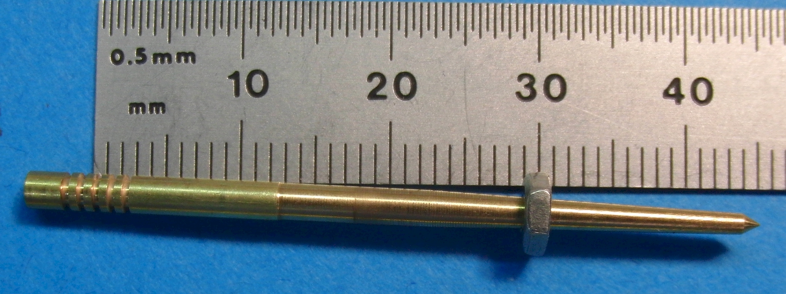
To illustrate the difference, a small nut is used to show where the diameters are equal. A small nut is placed on the needle as far as it will go on the taper. Then the distance from the nut to the lower edge of the second clip position is measured. (It is shown with the ruler for illustration only, actual measurement was made with a caliper)
First, here is the 4D92 with the nut. It measures 30.85mm from clip to nut.
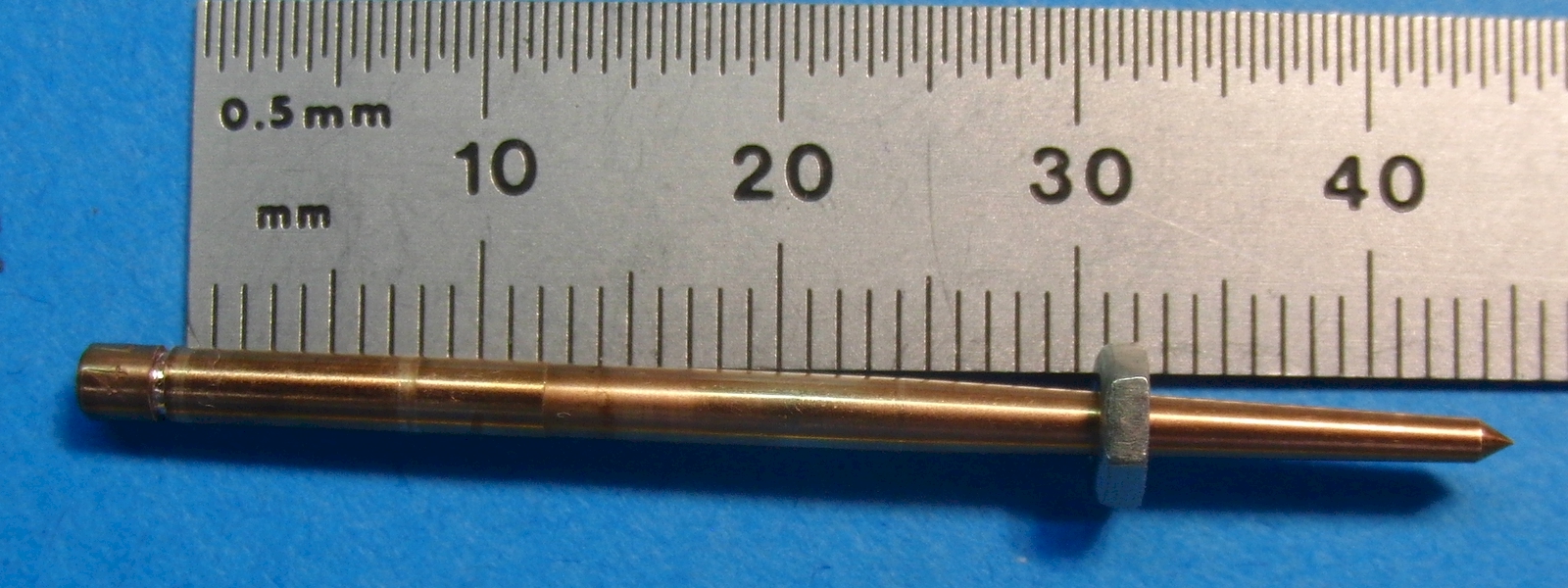
Next, here is the 4D93 with the nut. It measures 30.79mm from clip (2nd position) to nut.
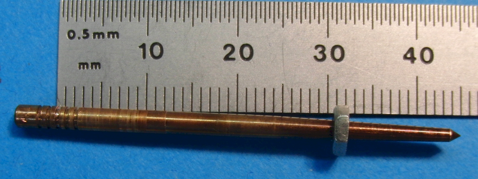
Finally, here is the non-marked needle with the nut. It measures 29.09mm from clip (2nd position) to nut.
This animation shows the difference.
Needle Retaining E Clips
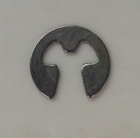
There are several different retaining clips for the various TK22 needles.
The factory E clip is not an industrial standard. It measures:
Needle shaft diam: 0.1022" (2.60mm)
Needle groove diam: 0.0780" (1.98mm)
E clip thickness : 0.0149" (.378mm)
E clip uninstalled OD: 0.2586" (6.57mm)
E clip installed OD: 0.2626" (6.67mm)
A Keihin clip can substitute for the TK22 factory clip. The part# and SKU# may be swapped below. One is a larger clip than the other. The larger clip is the correct one. If a substitute is needed and cost is not an issue (they are pretty inexpensive), it may be safer to order both parts and use the larger clip.
It is most likely Keihin clip #16115-169-0040. SKU:018-033. (Used on 2.9mm N427-48 needles.)
Needle shaft diam: 0.1142" (2.90mm)
Needle groove diam: unknown
E clip thickness : 0.0160" (.406mm)
E clip uninstalled OD: 0.2555" (6.49mm)
E clip installed OD: 0.2620" (6.65mm)
It may also possibly be Keihin clip #0403-802-1000. SKU:018-616. (Used on 2.6mm N427-46 needles.)
Needle shaft diam: 0.1022" (2.60mm)
Needle groove diam: unknown
E clip thickness : 0.0120" (.305mm)
E clip uninstalled OD: 0.2310" (5.87mm)
E clip installed OD: unknown
The Dynojet DN0205 needle is not compatible with the TK22 factory clips, nor is it compatible with either of the Keihin clips. Dynojet should be able to supply the clip, or maybe the Dynojet clip is an industrial standard clip.
Needle shaft diam: unknown (to four SF)
Needle groove diam: unknown
E clip thickness : 0.0172" (.437mm)
E clip uninstalled OD: unknown
E clip installed OD: unknown
The non-marked needle uses a slightly different clip. It is somewhat loose so the OD does not change when installed. It is also thinner. It is likely meant to use the same clip as the TK22's factory clip, but is loose enough that a smaller clip would work better. The above, smaller, substitute Keihin clip works on the non-marked needle, but it is rather tight. The non-marked needle's clip measures:
Needle shaft diam: 0.1020" (2.59mm)
Needle groove diam: unknown
E clip thickness : 0.0122" (.310mm)
E clip uninstalled OD: 0.2360" (5.99mm)
E clip installed OD: 0.2360" (5.99mm)
Comparing Needle Profiles
A qbasic computer program was written to compare the relative leaness/richness of needle changes for the different needles. The program compares the 4D93 and/or DNO205 needles. Here is the actual program (you will need a copy of qbasic to run this program):
TK22needleGraphic.BAS
Here is a diagram of the area that the computer program is actually investigating.
The program is setup to compare the amount of exposed needle-jet opening for two needles (or the same needle at different clip positions). If more area is exposed, the mixture is richer, and less area is leaner. It compares the relative richness/leaness for all throttle positions. The output shows percentage difference in exposed area (not percentage of actual richness or leanness). The comparison is done by selecting one needle and clip position (with or without shim) as the "reference" needle, then selecting another needle (or same needle) with same or different clip position (with or without shim) as the "test" needle. The plot shows how the test needle would perform compared to the reference needle. Here are some examples:
(The non-adjustable Kawasaki needle is the same as the adjustable Kawasaki needle at clip position 2.)
(Clip positions are counted from the top of the needle.)
As expected, it is richer at all throttle positions, but by varying amounts.
This graph shows the effect of switching from stock needle to Dynojet at 3rd clip.
The Dynojet needle is actually leaner at the very lowest throttle positions, but quickly becomes much richer at mid throttle openings. Then at higher openings, once again gets very slightly leaner.
This graph shows the effect of switching from Kaw needle at 3rd clip to Dynojet at 3rd clip.
The Dynojet needle is much leaner, here, at the very lowest throttle positions, but is approximately equivalent from mid throttle to full throttle.
This graph shows the effect of switching from Dynojet needle at 3rd clip to Dynojet at 4th clip.

As expected, the 4th clip is richer at all throttle openings, but much more so at lower throttle openings.
Also, notice in the 1/8th throttle or lower range, there is no difference in fuel flow showing on the graphs. This is because the opening of the needle-jet is occupied by the non-tapered portion of the needle in that range of throttle openings. The program registers this as no change in exposed needle-jet area, however, in fact, there will indeed be a change in fuel flow. This is because fuel flow will increase as the tapered portion of the needle approaches the mouth of the needle-jet. This is confirmed by o2 sensor readings.
These effects will act to make the graphs a lot less precise than they actually appear. This needs to be kept in mind when comparing the graphs.
From the above graphs, it is clear that changes to the needle make the greatest difference below 1/2 or 3/8 throttle.