Manometer Notes
Introduction:
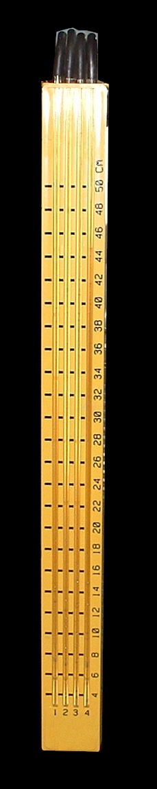
A mercury-manometer is a tool used for "synchronizing" multiple carburetors on multi-cylinder engines at idle. This means making the intake-manifold vacuum equal on all cylinders. The tool most commonly comprises of four individual, ridgid, clear plastic, mercury-manometer tubes (0.18" O.D.), parallel to each other, and sharing a common reservoir. Rubber tubing with 1/8" nom. I.D, and 0.100" nom. wall thickness, is used to connect the tool to the engine (which will typically have a 5.0mm brass port routed directly into the intake manifold). The typical tool measures the vacuum in centimeters of mercury, and is graduated from 0 to 50cm. These notes are written for this tool. The information gathered here is based on actual manometer experiments on an actual engine, along with experiments on a test-bench vacuum apparatus and analogous electrical circuit modeling.Type of manometer:
The reservoir is vented to the atmosphere, so the tool can be used as 1, 2, 3, or 4 individual manometer "channels" working independently. This type of manometer is called a gauge-pressure type manometer. This means measurements are relative to atmospheric pressure. If the vent is closed, all of the channels will affect each other. (This would be called a differential-pressure type manometer). The vent should be open for synchronizing and for manometer calibration (normalizing). When stored, all of the hoses should be plugged to prevent mercury vapor loss, or mercury spillage.Getting a smooth idle:
The purpose of synchronizing the carbs is to get each of the cylinders to do the same amount of work at idle. (At larger throttle openings, the small differences are insignificant.) This means, if all of the cylinders are the same, giving each one the same amount of air/fuel charge will make each cylinder do the same amount of work. Additionally, if each intake tract is the same, then making the average vacuum in each tract the same by adjusting the carburetor throttle, should ensure the same amount of charge goes to each cylinder. A typical motorcycle engine will have a vacuum reading in the range of 15 to 30 centimeters at idle. The actual reading is not important, nor is it necessarily an indication of motor condition. The importance is on the relative difference between cylinders.Worn engine problem:
If, however, there are differences in the cylinders, such as wear condition, a problem arises. A worn cylinder assembly will pull less vacuum than a good cylinder. This means its average vacuum will be lower than the normal cylinders. Synchronizing the carbs will require closing the throttle more on the worn cylinder in order to raise its vacuum level. The result is that the worn cylinder will be given less charge than the normal cylinders. Since a worn cylinder will do less work, even if given the same amount of charge as a normal cylinder, synchronizing the carbs with a manometer will actually make the problem worse, not better. Therefore, it is important that the cylinders are all in relatively similar condition for the manometer to successfully synchronize the carburetors to create a smooth idle. The best test for cylinder condition would perhaps be a compression and/or leak-down test. If the cylinders vary greatly, the problem should be corrected or a different method should be used to synchronize the carbs.Air bubbles affecting the reading:
The manometer indicates vacuum by noting how high the top of the column of mercury reaches on the graduated scale (centimeters or inches). However, if there are air bubbles in the mercury, the reading is not accurate. The air bubbles contribute no weight to the column of mercury, but they alter the height. When the manometer is hooked up and vacuum is present, the air bubbles can be removed by a syringe pulling air from the vent tube.
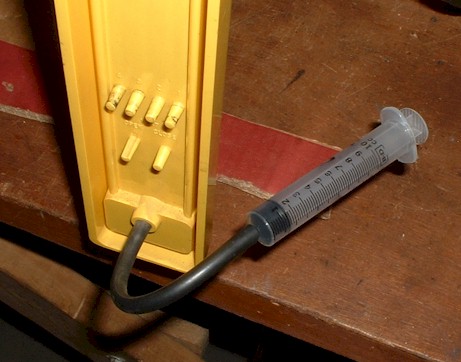
This is very simple and effective. All four columns will drop completely when the syringe is pulled. Then the syringe is slowly removed from the vent hose, and the mercury columns will rise slowly to their final levels with no air in the columns. If mercury comes out of the vent tube, there was too much mercury in the reservoir.
Checking for air leaks:
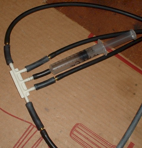
The syringe is also good for checking for air leaks. Using a 4-to-1 plastic manifold (Ford EGR vacuum manifold with 3/16" ports), , a syringe can be used to put a constant, steady vacuum on the manometer. The columns should rise to the same level and stay there as long as the syringe stays pulled. Beware; the plastic manifold has a molding imperfection, which may cause a leak. The imperfections can be removed with a razor or sandpaper.
Average vacuum:
On an engine, the manifold vacuum is not constant; rather, it comes in distinct pulses. Therefore, the instantaneous vacuum varies greatly, is difficult to measure, and is not a good indicator of airflow. The desired reading is actually the average vacuum inside the intake tract. That should give a better indicator of the amount of charge the cylinder is getting. (This assumes the cylinders are all of similar condition as mentioned above.) A good manometer will indicate the average vacuum in the intake tract as a smooth reading on the mercury. Ideally, the mercury will not oscillate up and down at all, but in a real manometer, some jitter will be seen in the mercury level.Volume affects the vacuum:
Since the vacuum is in pulses, and the air only moves in one net direction (due to the intake valve), the average vacuum level is affected by the volume of air in the intake tract. The larger the volume of air in the intake tract, the higher the average vacuum will be. (The upper limit would be near the maximum peak-vacuum the cylinder can produce. It should be noted, only idle conditions are being considered here. Further discussion of this phenomenon is available below.)Connecting manometer without a restrictor affects intake manifold vacuum:
This presents a problem when using a manometer. If a manometer is simply hooked up to the intake tract, the extra volume of air in the manometer tubing may affect the vacuum in the intake tract. Generally, the average vacuum will increase, and the manometer will indicate a higher reading accordingly. This is not an errant reading by the manometer; rather, it is the manometer affecting the vacuum in the intake tract. However, because the manometer is connected through a small port, the port acts like a restriction. This helps mitigate the effect of the increased air volume somewhat, but not totally. The restriction also alters the behavior somewhat. The volume of air in the tubing, along with the restriction of the vacuum port, would act a bit like a resonator. This means it will affect the average vacuum in the intake tract differently for different pulse frequencies. If the pulses are not "tuned", the effect will only be minimal. (Further discussion of this type of behavior is available below.)At first, it would seem that this effect on the average vacuum should not be a problem since all cylinders will be affected similarly. However, differences in manometer tubing (due to rubber thickness, pliability from temperature etc.) may yield a different amount of change for each cylinder. In any event, a measuring device should not alter the item being measured, so whether the effect is the same for all manometer channels or not, steps should be taken to remove the possibility of the manometer altering the vacuum.
Restrictor:
In order to prevent the air volume of the manometer tubing from affecting the average vacuum, a restrictor is placed just inside the opening of the manometer tubing, near where it connects to the intake manifold port on the engine. If the restrictor is far from manifold, the tubing of the manometer will possibly affect the vacuum level in the intake tract. It is important that the restrictor be as close to the intake tract as possible. It should also be much, much smaller than the intake tract, on the order of a pinhole.
Typically, the restrictor is a plastic plug with a 0.02" pinhole in it. The restrictor is placed about 1 inch into the tubing near the end connected to the engine. The pinhole allows a tiny bit of air to flow slowly from the manometer to the intake tract. When the average vacuum inside the manometer matches the average vacuum inside the intake, the net flow of air stops and only a tiny bit of pulsed air flows back and forth through the pinhole. The flow of pulsing air is so small that it is affectively negligible and will no longer alter the vacuum inside the intake tract.Dampener:
The restrictor also produces a natural dampener. The alternating flow is so small; the volume of air inside the tubing can accommodate it without affecting the instantaneous vacuum inside the manometer. This means the mercury level should stay very steady and easy to read. The exact size of the pinhole is not critical. It need only be much, much smaller than the intake tract itself. The exact size of the hole won't alter the reading, but only the speed with which the mercury can react. The smaller the hole is, the more steady or "slower" the mercury will be.False reading caused by cheap, plastic restrictor:
The restrictor dampens the mercury, but should not affect the average reading. However, there is a problem with some of the commonly available manometers on the market. The hole in the restrictor is not always perfectly cut. There can be a tiny flap of plastic partially blocking the hole. Because the air is pulsing back and forth through the hole, the flap of plastic can act somewhat like a directional valve. This affects the air in one direction more so than in the other direction. This leads to a false average reading. The reading may be high or low depending which way the flap is acting.Normalizing the tool:
Because there is a chance that the restrictors are affecting the reading in this manner, the tool needs to be "normalized". This means that if all four manometer channels are connected to the same, pulsing vacuum source, all four readings should be the same. To test this, the same 4-to-1 plastic manifold (Ford EGR vacuum manifold with 3/16" ports), as mentioned above, is used to apply the same vacuum to all four channels. The plastic manifold was previously available at most parts stores, but now Ebay is probably a better source.
A short hose is used to connect the plastic manifold to one cylinder of the engine at idle (in order to provide a pulsing source), and all four manometer channels are connected to the four remaining ports. When it is connected, the four channels should give identical readings. As mentioned above, no air bubbles should be visible in the mercury columns.
Correcting the plastic restrictors:
If the readings are not identical, they may be somewhat corrected by cleaning up the openings to the restrictor holes using a pin or small drill bit. Generally, this will take some trial and error. Also, because the adjustments are made at idle, they may not be accurate at higher RPMs. This is not a problem since the tool is really only meant to be used at idle.Better restrictors:
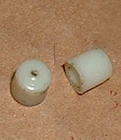
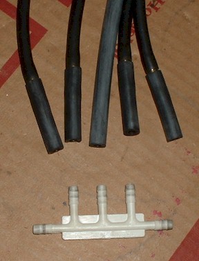
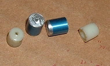
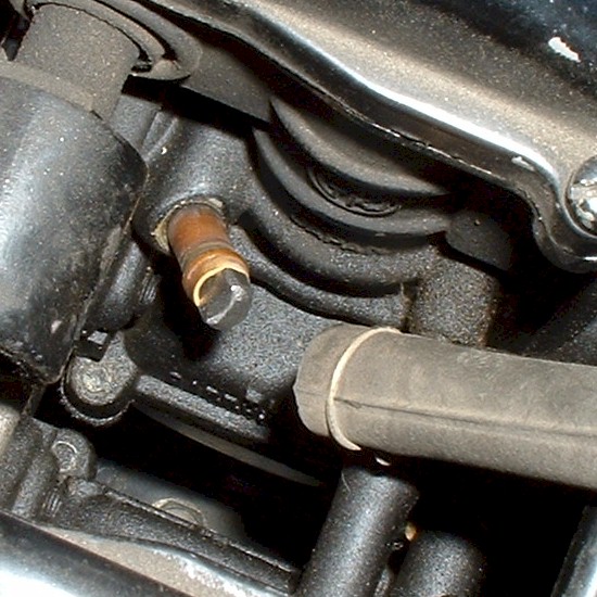
However, another, better option has been found. It is to abandon the 4 plastic restrictors altogether, and make 4 higher quality restrictors out of aluminum. Because the restrictors can be made longer (with a longer hole) they tend to be more restrictive, even though the hole diameter may be larger. This leads to a more stable manometer and a more accurate reading. Here are some photos of the original plastic restrictors (white) along with some homemade aluminum restrictors made from pieces of a 5.0mm O.D. (blue) knitting needle , with 0.031" I.D. hole.
It has been found that the aluminum restrictors needed no "tweaking" like the original plastic ones did, and were accurate at higher RPMs as well as idle. They were installed into 2" long, 3/16" nom. I.D., 0.100" nom. wall thickness, rubber tubes , which connect to the manometer through 3/16" O.D. brass couplers (4730-99-000-2012). This makes the rubber tubes replaceable as they wear from multiple uses, gasoline degradation, and stretch. The restrictors can be cut out and installed into new rubber tubes.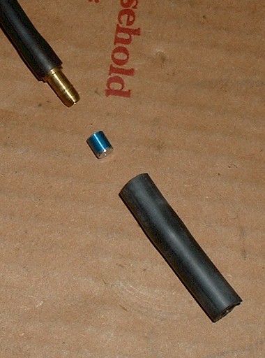
Vacuum tap problem (vacuum petcock etc.):
The affect of differing volumes of air in the intake tracts poses another problem. Often, there is a tap for a vacuum operated petcock. This means one cylinder will have a slightly larger effective volume of air in the intake tract. Theoretically, this means for an equal amount of throttle opening, (and identical cylinder wear condition) the cylinder with the petcock tap will get slightly more charge per cycle. In addition, it will register a higher average vacuum. This results in the throttle, for that cylinder, being opened further in order to match the vacuum readings of the other cylinders, and consequently, the cylinder gets even more charge. Luckily, in practice, the amount of affect the vacuum-petcock tap has is very minimal. It is typically in the range of .25 cm of mercury or less. The tap, along with the vacuum hose to the petcock, forms a similar pseudo-resonator as described above for the manometer tubing. The solution is the same. A restrictor could be placed into the vacuum port in order isolate the air in the hose from the intake tract. Since the affect of the vacuum-petcock hose is so minimal, nothing really needs to be done to correct it. (Further discussion of this type of behavior is available below.)Vacuum tap restrictor:
For academic reasons, a mod was created to reduce the affect of the petcock tap. A restriction should not affect the operation of the vacuum-petcock tap as it, like the manometer, operates with no net flow of air. The restrictor may delay the initial opening of the petcock by a fraction of a second, but that should not matter. The average vacuum, as seen by the petcock, will remain the same. The restrictor was created by simply grinding a flat surface onto the side of a bolt, cutting the bolt to length, grinding the head small enough to fit into the hose, and dropping the bolt into the vacuum tap. The head of the bolt should be just big enough so the bolt won't fall through the pipe into the engine. Also, a groove should be cut into the head of the bolt so air can flow past. The flat ground along the side of the bolt allows a pathway for air to flow. This path is small so it acts like a restrictor. With the restrictor, the vacuum petcock hose had no discernable affect on the vacuum reading. Without the restrictor, the effect on the vacuum reading was less than 2mm. (The petcock end of the hose was plugged, of course.) This shows, for the most part, the vacuum-petcock's effect on manifold vacuum, can be ignored (as long as it is not leaking air from the atmosphere), when synchronizing carbs. (Further discussion of the pseudo-resonator phenomenon is available below.)5mm bolt ground with a flat and cut to 25mm long on the shank for use on a TK22 carb.
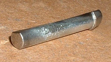
The head stops it from falling in, but must let the hose seal to the pipe, and have clearance for air to flow past.
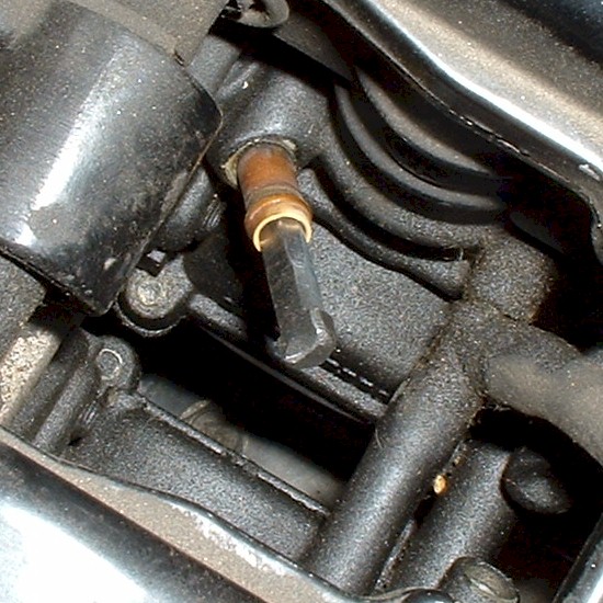
The hose should fit easily over the head.
Summary:
For a manometer to be useful in a carb-sync operation:--The cylinders must be of similar condition.
--All intake tract volumes must be equal.
--The manometer should have restrictors at the engine side of the connecting hoses.
--The restrictors should be checked so that equal vacuum gives equal readings on all 4 mercury columns.
--Any air bubbles should be pulled out of the mercury columns otherwise the readings will be inaccurate.
--Vacuum petcock connections and vacuum-operated emission devices do not affect the sync by any significant amount, as long as they are not leaking.
Each experiment was performed with an oscilloscope to view the instantaneous voltage at (a) or (b) or both. A very rough sketch was made of each waveform. The rough sketches show the shape, but not necessarily any actual dc level.
Later, the circuit was altered to include an inductor at the connection of the separate volume (hose) in order to better model the affects of the mass of the air. This models the momentum of the air, which produces a more accurate representation of a resonator. Since the underlying effect of the resonator did not really change with the addition of the inductor, it was not investigated further.
Here is a schematic for the circuit:
In the model, vacuum is represented by negative voltage. Airflow is represented by electrical current. A volume of air is represented by a capacitor. A restriction in the airways is represented by a resistor. The intake valve is represented by a switch (actually a transistor). And the negative voltage source produces the vacuum. Electrical ground represents atmospheric pressure. A dc voltmeter measures average voltage much like a manometer measures average vacuum. Because there is no net current flow from (a) to (b), those points will have the same average voltage, (but not necessarily the same instantaneous voltage). However, since a voltmeter uses a tiny bit of the circuit's current to measure the voltage, connecting the voltmeter to a branch separated by a very high resistance will result in slightly different average values for the point the meter is connected to. A manometer does not have this drawback. Measuring the average at point (a) is really all that is necessary for most of these experiments, and the voltmeter will be accurate at that point.A note about average voltage on a resistor:
The average voltage on a resistor determines the average amperage through the resistor. If two identical resistors have the same average voltage on them, regardless of instantaneous voltage, they will have the same average current through them. (The average power dissipation may, however, be different.)Volume of intake tract, electrical model:
Experiment 1 shows the affects of the volume of the intake tract. As the volume increases, the average vacuum increases. In the circuit, the minimum theoretical value is -1.15v, and the maximum is -4.49v. These values are calculated using standard circuit analysis methods.Volume of intake tract, shop-vac model:
To verify the behavior seen in the electrical model, a little experiment was done using a shop-vac, some tubing, a syringe, and a small pinhole restrictor. The diagram below shows the setup:
Rapidly pinching the hose shut and releasing repeatedly, at the indicated pinch point, will simulate the action of the intake valve on the engine. As the syringe is pulled and held steady, the volume in the intake tract becomes larger, and the average reading on the manometer will increase. Note that the extra volume of air does not even need to be in the path of the general airflow for the effect to be seen. The shop-vac model appears to agree with the electrical model.Restrictor experiment:
Since it has been demonstrated that changing the volume of the intake tract affects the vacuum in the intake tract, the next experiment was to determine if the affect of changing the volume can be reduced by separating the extra volume with a restrictive opening. Experiment 2 shows that if the restrictor has sufficient resistance to flow, it can isolate the intake tract such that the extra volume has almost no effect on the average vacuum in the intake tract. The results show that as the resistance was increased, the extra volume had less and less effect on the intake tract. This shows it is important to make the restrictor opening as small as is practically possible while still allowing enough opening so that the manometer can still function. Doing this will make the manometer a much more accurate tool.Resonator experiments, electrical:
The next experiments show the effects of increasing the volume of an intake tract through a restrictor with insufficient resistance to isolate the extra volume. Experiments 3 and 4 show that if the extra volume is coupled with an insufficient resistance, not only does the average vacuum increase as the secondary volume increases, but the average vacuum will peak at some finite amount of extra volume. Adding more volume beyond that will result in the average vacuum reducing slightly from the peak. This would indicate that the extra volume and restriction behave somewhat like a resonator. (The circuit model may not be a true resonator since there is no inductor involved. The inductor model was investigated later.) Experiment 5 shows that if the main intake tract volume is already very large, the secondary volume only has minimal effect on the average vacuum in the intake tract.Resonator experiments, actual resonator:
The resonator model was tested on an actual, 4-cylinder, 4-stroke engine. A large, 65ml syringe was connected to the vacuum-petcock port on cylinder number 4 while a manometer was connected to the normal manometer port. Also, cylinder 1 was connected to the manometer for simultaneous comparison. The syringe was adjusted while the engine was running at idle (1250 RPM). The idle did occasionally fluctuate by 10 RPM or less, as it normally does. There was no observable correlation between syringe movement and the RPM fluctuations, (though one was expected).The vacuum behaved similarly to what was predicted in the electrical model. When the syringe was all the way closed, the vacuum reading was noted. As the syringe was pulled, then held steady, a reading was taken. At first the vacuum increased as volume increased then as the volume increased, the vacuum readings began to drop back to the level when the syringe was closed. The maximum vacuum increase was when the syringe was pulled to about 25ml and the increase was about 1-1/2 cm. An illustration of this experiment is seen in the diagram below.
Intake tract differences detrimental to sync. :
Much in the same way that unevenly worn cylinders work against synchronizing carbs, so do unequal intake tract volumes. Whether the increase in vacuum is from a larger intake tract volume, or from a connected resonating chamber, if it is only on one cylinder, it will negatively impact attempts to equalize air/fuel delivery across multiple cylinders. The increase in volume can increase the average vacuum, which increases average air/fuel delivery slightly. Since the vacuum is registering higher, the remedy is to open the throttle until the vacuum matches the other cylinders. This results in even more air/fuel flowing. This is the opposite of what was needed. The average vacuum is matched, but now one cylinder has its carb throttle open more than the others.