Neutral Switch Trigger
to Turn On Headlight

Headlight Triggered by Neutral Switch
Designed by Louis Dudzik 2/19/08
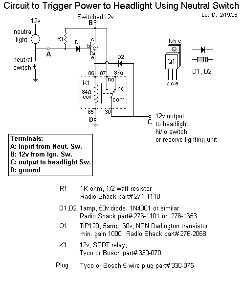
In order to get as much power as possible to the starter motor of a motorcycle, it is beneficial to have the headlight turned off during starting. Many motorcycles in the U.S. were not equipped with a switch to turn off the headlight. This circuit was designed to leave the headlight turned off until the bike is taken out of neutral for the first time, presumably after it has already been started and is running. This eliminates the need for a bar-mounted auxilliary switch which may be deemed unsightly.If the bike is equipped with a "reserve lighting unit", this device feeds power to the reserve lighting unit instead of directly to the hi/lo beam switch.
This project was designed for Kawasaki KZ motorcycles, but may apply to many other makes and models.
......Parts List:.....R1
1K ohm, 1/2 watt resistor
Radio Shack part# 271-1118D1,D2
1amp, 50v diode, 1N4001 or similar
Radio Shack part# 276-1101 or 276-1653Q1
TIP120, 5amp, 60v, NPN Darlington transistor
min. gain 1000, Radio Shack part# 276-2068K1
12v, SPDT relay,
Tyco or Bosch part# 330-070Plug
Tyco or Bosch 5-wire plug part# 330-075Notes:
When power is first applied to the circuit, and the neutral switch is closed (in neutral), K1 is de-energized. There is no power output to the headlight. Because the neutral switch is closed, the base of Q1 is held low. Q1 is in cutoff. When the switch opens, current through the neutral light and R1 is no longer shunted to ground. This means the voltage on the base of Q1 jumps up to near battery voltage (~12v). This turns Q1 active and power is applied to energize the K1 coil. When the relay contacts move, power is applied to the headlight and, through D2, another source of power is applied to the K1 coil. This second source of power holds the K1 relay energized until all power is removed by shutting off the bike.The base-emmiter junction of Q1 is approx. 1.2 volts. Q1 does not saturate, but stays in the active region when not in cutoff. Because Q1 is only used momentarily, it does not need a heatsink.
The neutral switch works normally to turn on the neutral light.
R1 is only needed as a safety in case the neutral light bulb burns out. If the bulb burns out, R1 provides the power to activate Q1. R1 has continuous current through it whenever the neutral switch is closed. This means it dissipates about 1/8 of a watt when the bike is in neutral. It was chosen as a 1/2 watt resistor in case the circuit is enclosed in silicone and won't cool as rapidly.
D1 is needed as a safety to protect Q1 from excessive emitter-base voltage. Q1 is only rated to handle 5v there, but there will potentially be 12v there. D1 provides up to 50v of protection. D1 is only active momentarily, so heat is not a concern for D1.
D2 is needed to block the headlight load from Q1. Without it, Q1 would attempt to turn on the headlight while energizing K1. This would burn out Q1. D2 has up to .25 amp through it continuously. It was chosen as a 1 amp diode to provide a safety margin. If D2 is to be encased in silicone, the silicone should not be excessively thick (preferrably less than 1/8 inch thick) so D2 can remain cool.
The circuit needs about 10v to activate, but once active, it only needs about 5v to stay activated.
It should be noted that the relays are somewhat susceptible to vibration. They should be mounted so they are isolated from engine vibration.
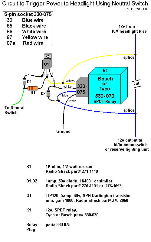
Here is a pictorial view of the circuit:

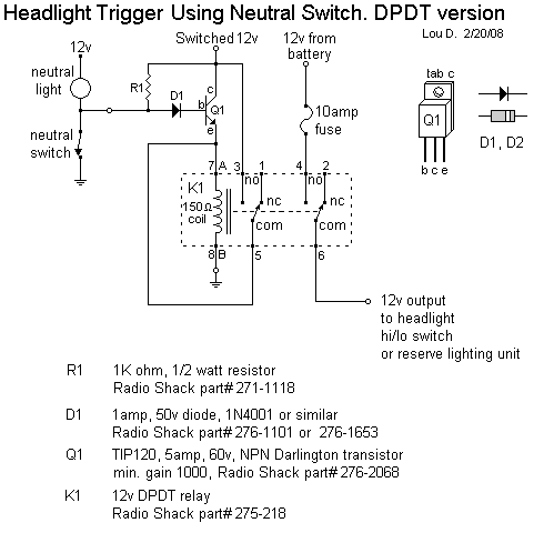
If K1 were to be a DPDT relay, D2 could be eliminated, and the headlight circuit could get power directly from the battery rather than through the ignition switch, as the stock configuration requires. However, this requires a more expensive relay. Here is the DPDT version:
