Introduction:
This project is to adapt a 7-pin General Motors High Energy Ignition (HEI) module to provide spark for any Kawasaki KZ motorcycle originally equipped with points. It can also be used on any vehicle incorporating a 12-volt, negative-ground electrical system using a standard Kettering-style ignition system. The 7-pin HEI module can be found on a 1986 Chevrolet Caprice 5.7L, 4BL, V-8.
Purpose:
The purpose of this project is to use the HEI module in order to reduce wear on the points. It also eliminates the need for the condenser and will allow the use of lower resistance ignition coils in order to get a higher-energy spark at the plugs. It will also allow the elimination of any ballast resistor as long as the ignition coil's primary resistance is 2.2 ohms or higher. This project will also automatically shut down the ignition system if the motor stops running. This is known as a time-out. This means the coil will be discharged after a set period of time and will not charge again until the points start to open and close again. This will prevent damage to the coil in the event the ignition switch is left on while the crankshaft is not turning.
Overview:
This project is designed to work with the stock points and the stock ignition coils. Aftermarket coils can be used, and any ballast can be eliminated, as long as the coil's primary-side resistance is not less than 2.2 ohms. The 2.2-ohm limit is imposed to prevent the HEI's internal current-limiter from becoming active. When it is active, more heat is generated inside the HEI module. In the interest of reliability, it is best to avoid unnecessary heat generation in the HEI module.One project circuit is required for every ignition coil. Therefore, a 4-cylinder KZ will require two circuits.
In order to use an HEI module with points, a small adapter circuit is required between the points and the HEI module. The adapter is basically an inverter. The points go from shorted to open in order trigger a spark. This means the voltage on the point go from 0 to some higher level (low to high) when a spark is to occur. The 7-pin HEI module triggers a spark when the input voltage goes from a higher voltage to a low voltage (high to low). The signal from the points must be inverted to operate the HEI correctly.
There are 3 circuits described here. In the accompanying drawing, they are labeled Circuit 1, Circuit 2, and Circuit 3. Please refer to them in the following descriptions.
7-pin HEI Module:
To describe this project, some background should be given about the HEI module. Please download the link below for notes on the 7-pin module.Basic Circuit (Circuit 1):
Circuit 1 is the basic inverter circuit with a time-out function.By default, R2 supplies voltage to the E terminal of the module. This is a signal to energize the coil by shorting the C terminal to ground. This only happens if the module is in "run" mode, and the transistor Q1 is not active. When Q1 is active, it shorts out the voltage of the E terminal.
When the points are open, R3 supplies voltage to charge capacitor C1. This puts voltage on the B terminal of the HEI module and enables the module into "run" mode. R3 also supplies voltage to R1 which then activates transistor Q1. While the points are open, then, Q1 shorts out the E terminal thus preventing the charging of the ignition coil.
When the points are closed, the voltage on R3 is shorted to ground through the points. This means the capacitor C1 is no longer charging, but will start to slowly discharge through the B terminal. Diode D1 is to prevent the capacitor from quickly discharging through the points. Since the voltage on R3 is now shorted, Q1 is no longer active and thus the voltage on the E terminal is allowed to jump up to a positive value. This is the signal to the module to start charging the coil. Terminal C is shorted to ground and current starts to flow in the coil.
The voltage on C1 is slowly dropping. If the points stay closed indefinitely, the voltage on C1 will drop low enough such that the module can no longer stay in "run" mode and the coil current will be shut off. This is a time-out condition. A spark will occur at this time. The length of time until the timeout occurs is determined by the capacitance of C1 and the internal resistance of the module. Since modules differ from brand to brand, a precise estimate for the time-out period cannot be made. It is roughly somewhere between .5 second to 2 seconds. More capacitance can increase the time.
If the points open in a sufficiently short enough time, Q1 will be activated to short the E terminal once again and the coil current will be turned off which will result in a spark at the moment the points open.
The cycle will repeat itself as the points continue to open and close.
LED Option (Circuit 2):
Circuit 2 adds an LED option as an indicator of the points position. When the points are closed, the LED is on brightly. When the points are open, the LED is off or very dim. Resistor R4 acts as a safety in case the LED fails. R4 also acts to ensure the LED is very dim or off by bleeding away current from the LED.
Bypass Option (Circuit 3):
Circuit 3 adds a DPDT switch and the condenser to allow for normal points operation in case the module or adapter circuit fails.
Notes on points condition
As the points get dirty, the voltage on the points will not go to zero when closed. It will stay above a certain value. When this happens, the coil-charging signal will stop functioning, and/or the timeout circuit will stop functioning. It is desired for the coil-charging to stop functioning before the timeout circuit fails. Therefore there is a limit to how dirty the points can get before the coil-charging function must stop. The timeout circuit will stop functioning when the point's voltage stays above 1.3v. So the coil must stop charging when the voltage on the points stays above 1.1v or so. Using the 10K resistor allows for the coil-charging function to stop functioning when the points voltage fails to drop below 1.1v. The timeout circuit continues to work.It is recommended that the points get cleaned periodically. They should not get pitted, but dirt may accumulate on the points over time. It should only require a quick wipe with a clean cloth and maybe a touch of contact cleaner. The point's cam-lobe should be lubricated as normal as well as the advancer unit.
Construction:
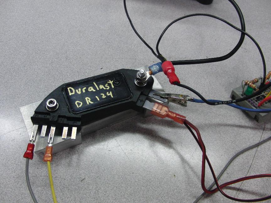
The adapter circuit takes very little power and should work fine even if sealed in silicone sealant. The HEI module will get slightly warm to the touch and should be mounted to an aluminum heat sink. The sink should be at least .1 inch thick for rigidity, and should have at least 6 square inches of surface area open to air. The HEI module used for this project was a Wells model DR124.
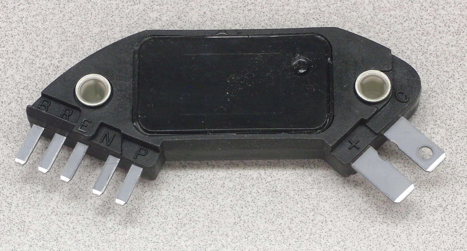
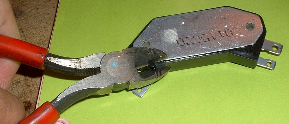
There are two plastic locator pins on the bottom of the module, which should be cut off in order to mount it flush to a plate. Of course, the plate could just as well be drilled to accept the pins.
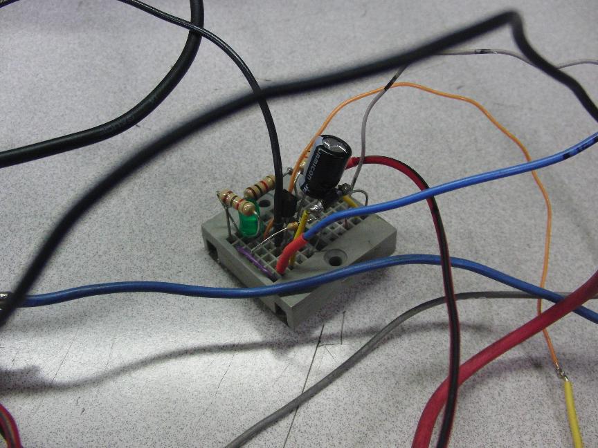
Here is the adapter board for the prototype.
A module being tested.
The circuit was initially tested on an electric motor fitted with points.
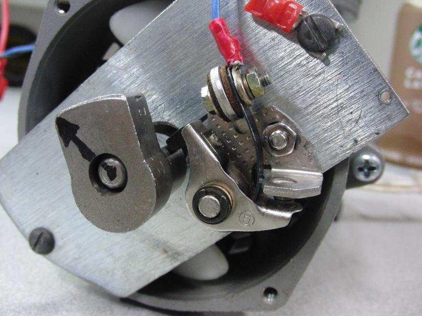
https://youtu.be/x3bCfUaXE68
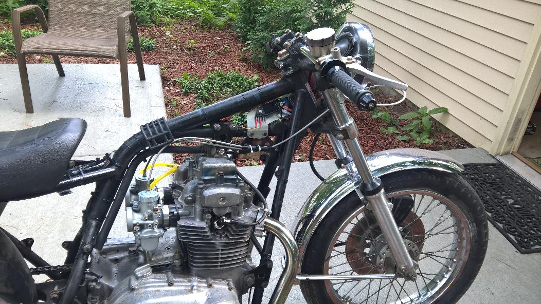
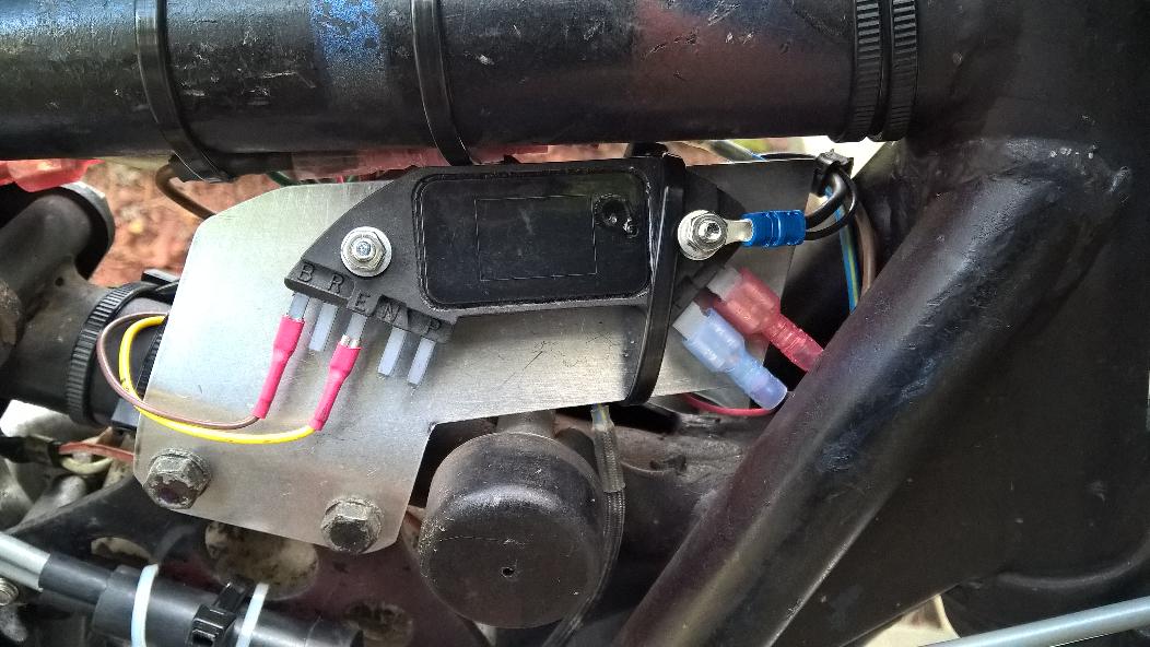
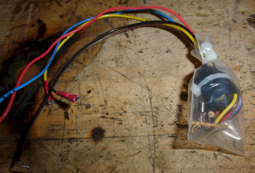
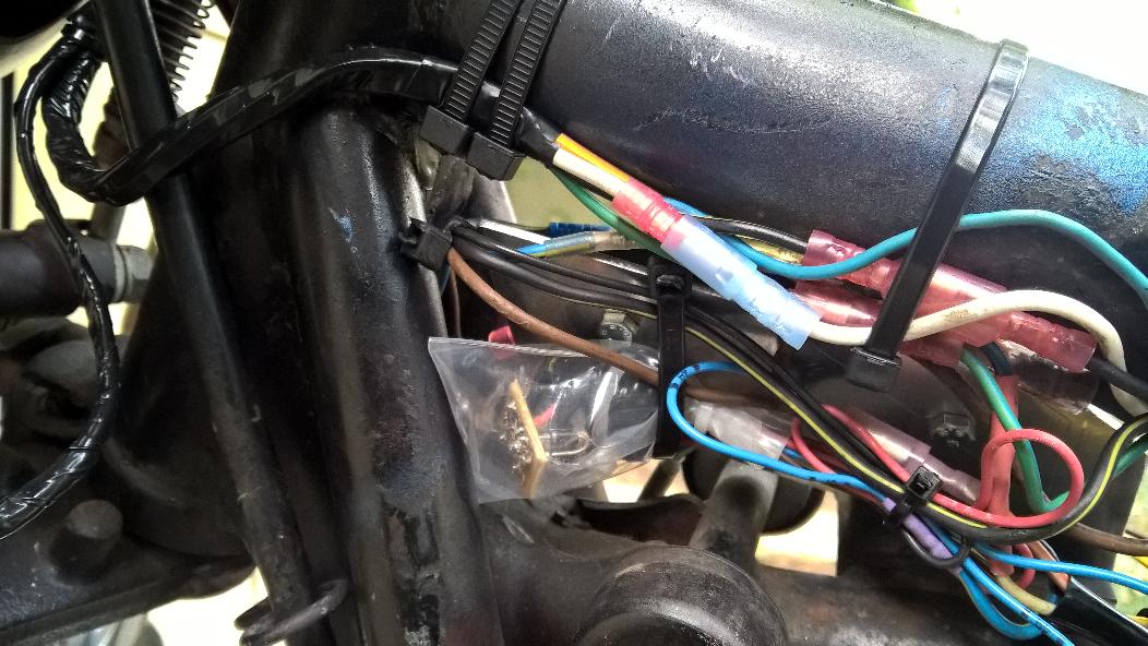
The project was installed onto a pair of KZ400's in summer of 2019 and continue to run. The video above was on a Kz400D4. The photos below were from a Kz400D3.
Conclusion:
Circuits 1 and 2 were assembled and hooked up to a test rig to simulate an engine. Each performed very well. Circuit 1 has been working well on two bikes using old, pitted points that were cleaned up slightly to run. The igniter circuit greatly improved running and starting. The bikes ran very poorly before the igniter circuit was installed. This page will be updated if any reliability issues arise.