GM HEI Ignitor Substitute
For a Kawasaki Gpz550
(Adaptable to other bikes)
Ignition Module For 1981 Kawasaki GPZ550 Using HEI Modules
Designed by Louis Dudzik 8/05 update 6/10/15
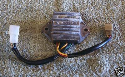
UPDATE : It is important to use the correct type of 4-pin HEI modules as there is now a new type available, which may NOT work for this project. Make sure to use the DR100 type modules, or one from the same family as described in the HEI module notes. Click on the link below for notes on the GM modules and notes on how to determine the correct type is being used.This project is an ignition module designed to replace the stock unit for a 1981 Kawasaki GPZ550 motorcycle. It uses two GM HEI ignitor modules. The parts for this project should not cost much more than $35. This module is designed to work with the stock inductive pickups and the stock spark coils. Aftermarket coils can be used as long as the primary side's resistance is not less than 2.2 Ohms. This module will also work as a replacement for other Kawasaki motorcycles that use the same stock unit as the GPZ550. Here is what they look like:
Click this for my notes and compatability cross-reference info on the stock Kawasaki KZ electronic ignitions. GPZstockIgnitionNotes.txt
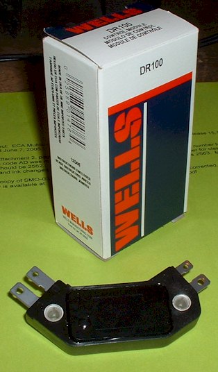
Click this for my notes on the stock Kawasaki KZ electronic ignition's RELUCTOR waveform. KzRelucSignalApprox_copy.GIFBecause the GPZ550 has an inline, 4-cylinder engine, it requires two spark coils, two pickups, and thus, two igniter circuits. This replacement module (as well as the stock unit) actually contains two separate ignition circuits using two HEI modules acting independently. The Wells model DR100 or Niehoff model DR400cs seem to be the same unit. These are what the HEI modules look like:
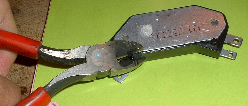
The construction is simple, but first you have to clip off the two locator pins on the bottom of the modules.
Then just mount the two modules on to an aluminum plate using the supplied thermal gel and appropriate bolts. The plate needs to be at least 1/8 inch thick to be rigid. It should probably have at least about 9 square inches of surface area for adequate cooling. (It only gets slightly warm). The bolts will act as the ground connection. Next solder or use connectors to attach the wires. The 3 external components can simply be soldered and wrapped in tape. Make sure the polarity is correct on the two diodes by paying attention to the stripe on the diodes. The resistor can go either way.
Here is what the somewhat crude and ugly prototype looks like on my bike:
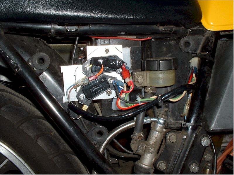
The module was installed in 8/05. The module currently (as of 8/07) has several thousand miles on it. If any reliability issues come up, I will update this page.
For those who would like to confirm it works before installing on the bike, here is a wiring diagram of how to bench test the circuit.:
To test the circuit, you tap the pickup cores with a screwdriver. This is the same test method for the stock ignition, as described in the manuals. The pickup with the black and blue wires will fire the 1 & 4 ignition coil. The pickup with the yellow and red wires will fire the 2 & 3 ignition coil.
Make sure the spark gap is about 1/4" for testing. Really good coils will be able to arc over 1/2 inch, but that will be stressing the coils. Going to 3/4 inch can damage the coils and/or the igniters by degrading their ability to create higher voltages.
Another test can be done without the adapter circuit and pickups. This will test the coils and igniters only.
Pressing one button briefly and releasing, will charge one coil and generate a spark. Do not hold the button for any extended period of time.
Due to the internal dwell compensation circuit, there may be a delay before firing, or a delay before the next time it can fire. This is normal, and will not occur during normal operation.
Make sure the spark gap is about 1/4" for testing. Really good coils will be able to arc over 1/2 inch, but that will be stressing the coils. Going to 3/4 inch can damage the coils and/or the igniters by degrading their ability to create higher voltages.
Here is a diagram for a KZ twin version. This is for an 82 KZ750 m1 csr twin. It can be used on some KZ400's and KZ440's as well, if they have the mechanical advancer with reluctor rotor and reluctor pickup.