Warning:
2. It is very important to not install the camchain tensioner while its cap and crosswedge are in place.
1. It is very important that the valve cover does not get installed while the tensioner is installed with cap and crosswedge in place.
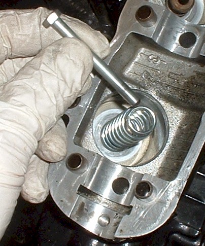
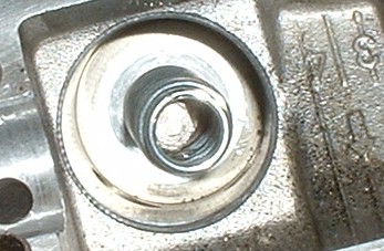
Remove the 17mm cap, crosswedge, and spring from the tensioner before installing the valve cover.
Remove the 17mm cap, crosswedge, and spring from the tensioner before installing the tensioner.
The tensioner puts slight tension on the camchain, but the real tension in the camchain is derived from the rotation of the crankshaft pulling the camshafts. The tensioner's job is to simply take up the slack on the loose section of the chain, and not give it back. It does this by lightly extending the tension rod, but not allowing the rod to retract. When the tensioner is at it's set position, the foot of the tensioner presses outward, due to the main spring, with a constant force of 14 to 16 pounds, with the crosswedge removed. The crosswedge and crosswedge spring will impart a very slight forward thrust to the foot as well.
Because the valve cover is part of the chain guide system, it presses down on the chain in between the camshafts. If the chain is already tight, and the tensioner has taken up the slack in the chain, (which it does automatically), when the cover is installed, the cover will press down on the chain making the chain tension much higher than it should be. This will lead to chain stretch, chain-guide wear or breakage, and in extreme cases, can break a camshaft. The chain stretch and guide wear are what will most likely happen. This happens without any symptoms other than shortened life of the camchain and guide system.
The same thing can happen if the tensioner is installed into the motor while the cap, crosswedge, and crosswedge spring are in place. The tension rod will be fully extended, and installing the tensioner will force the tensioner to retract and put very high tension on the camchain. When the motor is run, the tension on the camchain will be too tight. The motor then puts much higher tension on the chain while its running.
Normally, the guide system has a little give to take up minor variances in chain tension while the bike is running, but with the initial tension being too high, the guide system will not have enough give left over to allow for the variances. The result is stretched chain and/or guide damage.
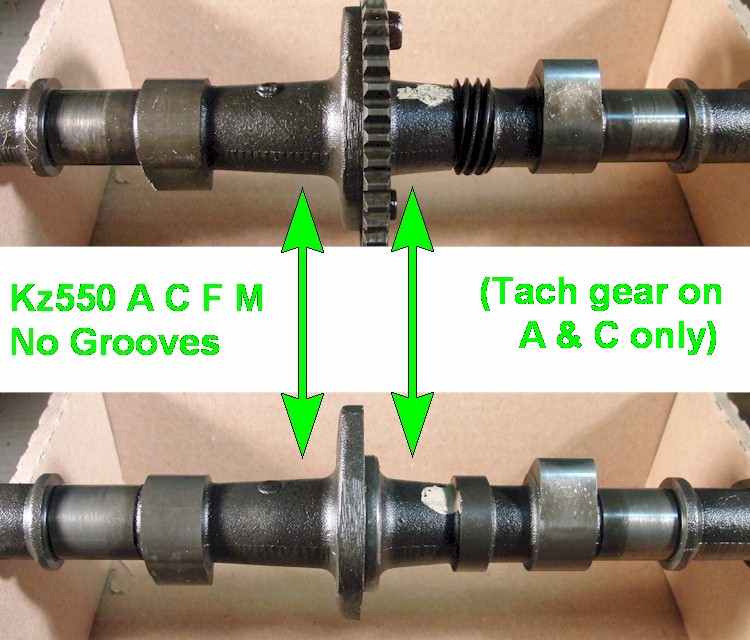
The standard grind (12044-1003 & 12044-1004) is identified by having no grooves cast into the camshafts.
These cams are found on these models:
Kz550 A1 to A4 (Standard model).
Kz550 C1 to C4 (Ltd Chain model).
Kz550 F1 to F2 (Spectre Shaft and Ltd Shaft models).
Kz550 M1 (Ltd Shaft model).
These all use the same grind for intake and exhaust.
Some exhaust cams will have a tach drive gear machined into the blank.
(12044-1004) has a tach drive.
(12044-1003) has no tach drive.
Models with a tach drive are:
Kz550 A1 to A4 (Standard model).
Kz550 C1 to C4 (Ltd Chain model).
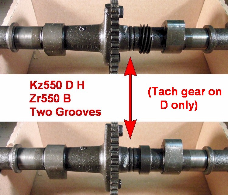
The first performance grind (12044-1034 & 12044-1035) is identified by two grooves cast into the camshaft.
The two grooves are just to the right of the timing sprocket.
These cams are found on these models:
Kz550 D1 (Dual Shock, 7-spoke, Gpz model).
Kz550 H1 to H2 (Mono Shock, 5-spoke, Gpz model).
Zr550 B1 to B4 (Zephyr model).
These all use the same grind for intake and exhaust.
Some exhaust cams will have a tach drive gear machined into the blank.
(12044-1035) has a tach drive.
(12044-1034) has no tach drive.
Model with a tach drive is:
Kz550 D1 (Dual Shock, 7-spoke, Gpz model).
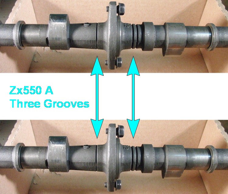
The second performance grind (12044-1059) is identified by three grooves cast into the camshaft.
Two grooves are just to the right of the timing sprocket (same as in the first performance grind).
A single, third, groove is just to the left of the timing sprocket.
These cams are found on these models:
Zx550 A1 to A3 (Mono Shock, 3-spoke, Gpz model).
These all use the same camshaft for intake and exhaust.
The position of the intake camshaft is advanced, relative to the exhaust, by the intake sprocket.
They also get the same stamping applied.
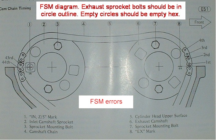
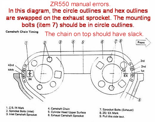
The intake and exhaust sprockets for all models get four holes drilled. They are in the circle and hex outlines.
The intake sprockets for the Kz400J and Zx550A models get an additional two holes drilled in the square outlines. These two additional holes allow the intake cams to be advanced.
4-hole sprockets have part number 12046-1019.
6-hole sprockets have part number 12046-1020.
Then the sprocket teeth are machined into the edge, along with heat treatment.
The Factory Service Manual's camshaft specs imply the Zx intake sprocket advances the camshaft by 10 crankshaft degrees, but some actually measure closer to 7 crankshaft degrees. This may be due to a machining error on the teeth of some sprockets.
It's generally not off by enough to make a large difference and no remedy is needed, but it should be noted anyway.
How it was measured.
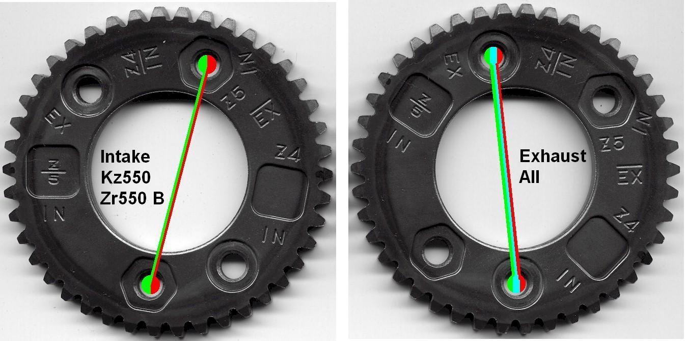
Here are how the Kz550 and Zr550B sprockets look.
Both are part (12046-1019).
Here are how the Kz400J and Zx550A sprockets look.
Exhaust is (12046-1019).
Intake is (12046-1020).
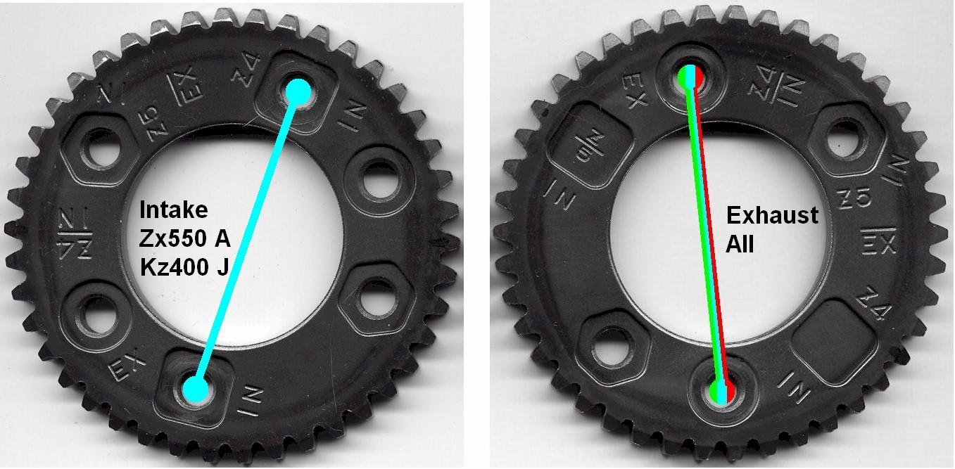
Notice the camshaft mounting holes are not in line with the center of the sprocket. This is so the camshafts cannot be mounted 180 degrees inverted.
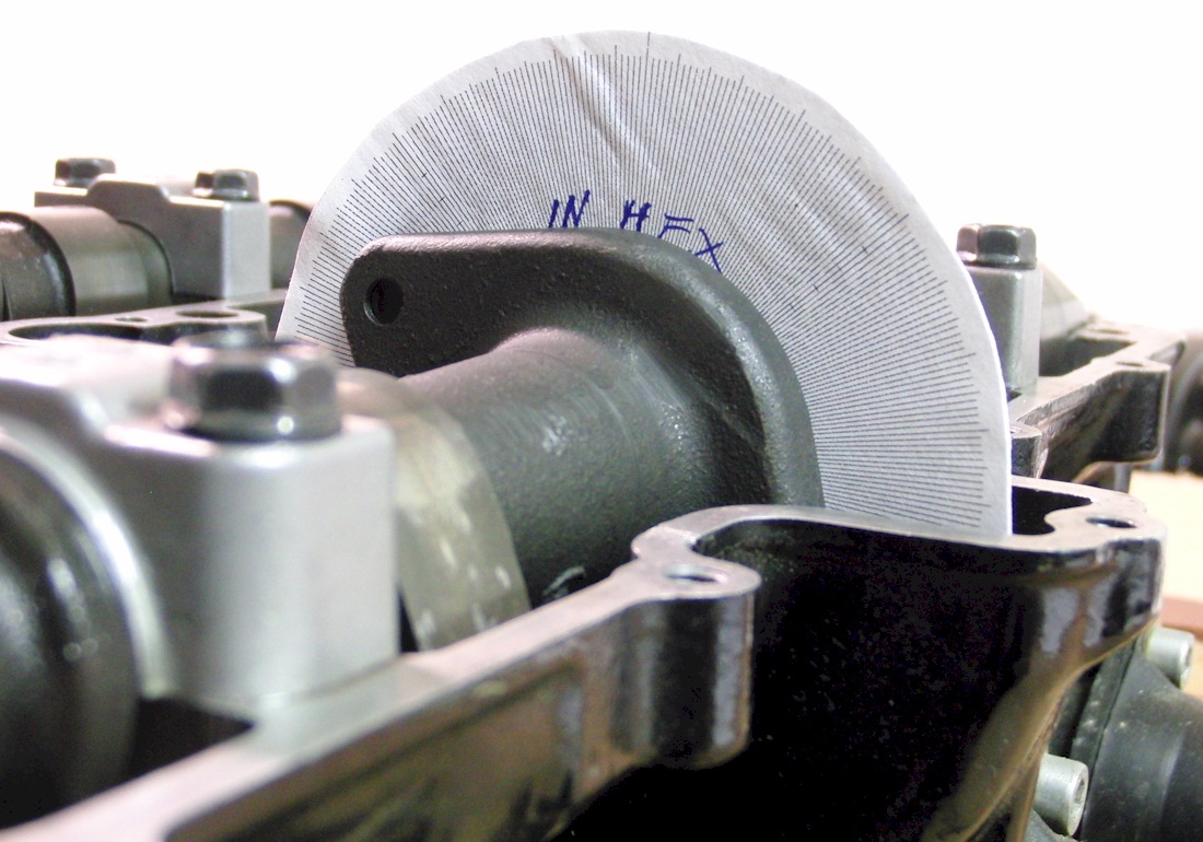
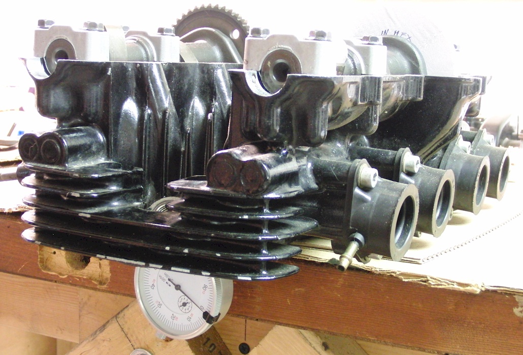
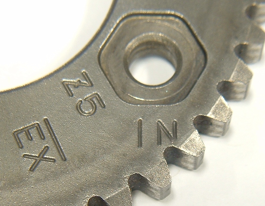
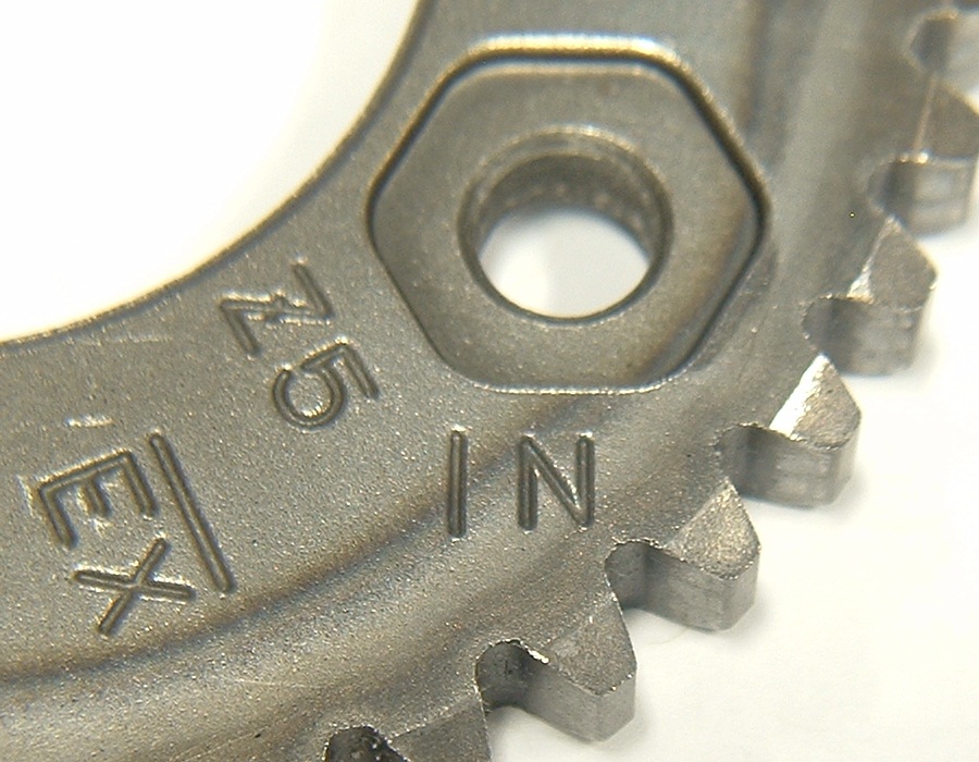
Older sprockets can be identified by the "IN" stamping near the hex outline. The lower right corner of the N is cut off.
Later sprockets have the "IN" slightly moved over to the left. Other than this superficial difference, they are identical.
The second performance grind may provide more performance than the first performance grind , but it is not yet known if they can be simply swapped into Kz550 D and Kz550 H motors without valve-to-piston interference. It may depend on whether the Z/5, standard intake timing is used, or the Z4/IN, advanced timing is used. The standard Z/5 timing should allow for more clearance. The Z/5 intake timing reportedly produces better performance in the Gpz motors anyway, including the Zx550A motors. It may even be worth changing the Zx550A intake timing to Z/5 on those motors at the next shim adjustment.
The Kz550 A, C, F, M and Zr550 A, B have 9.5 : 1 compression.
The Kz550 D, H and Zx550 A have 10.0 : 1 compression.
However, the Zx550 A pistons have a higher dome and deeper valve reliefs than the Kz550 D and H.
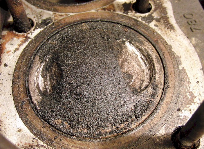
Here are the Kz550 D and H pistons.
The dome is roughly 4.1 mm tall (above the squish band surface).
The exhaust valve reliefs are roughly 2.5 mm deep (below the squish band surface).
The intake valve reliefs are roughly 3.6 mm deep (below the squish band surface).
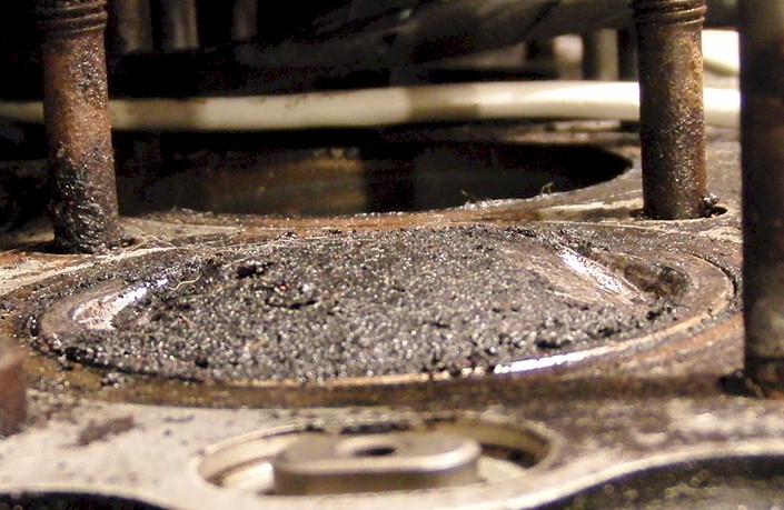
Here are the Zx550 A pistons.
The exhaust valve reliefs are roughly 4.8 mm deep (below the squish band surface).
The intake valve reliefs are roughly 5 mm deep (below the squish band surface).
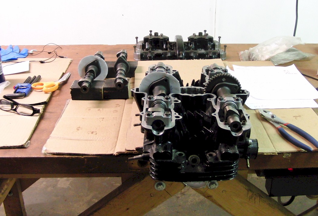
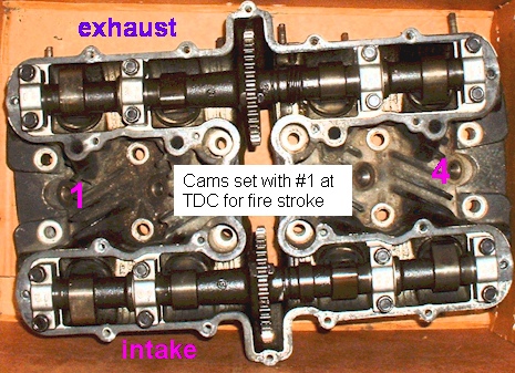
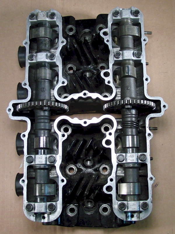
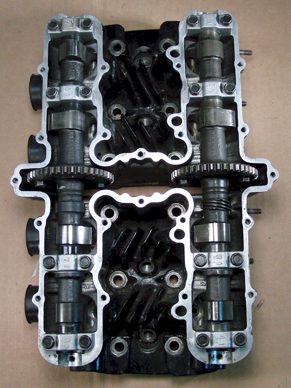
When the camshafts are set with the #1 piston at TDC, the exhaust lobe for cylinder #1 should point forward, and the intake lobe for cylinder #1 should point backward. Here is a photo.
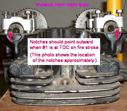
Looking at the ends of the camshafts from the right will show the notches in the ends of the shafts roughly pointing away from each other as in this photo. (The notches point the same way as the cam lobes on the #1 cylinder, which is the opposite way the cam lobes point on the #4 cylinder.)
These photos show the cam lobe positions, and sprocket positions, in normal firing order ( 1 2 4 3 ).
Notice the cylinder under fire has its cam lobes splayed outward.
Click on the image to enlarge it. Use the return button to get back here.


These animations are not synced together, but reloading the page, after some time, may sync them up.
The animations, on the right, pause when cylinders 1, 2, 4, and 3, are at TDC (or very close to TDC).

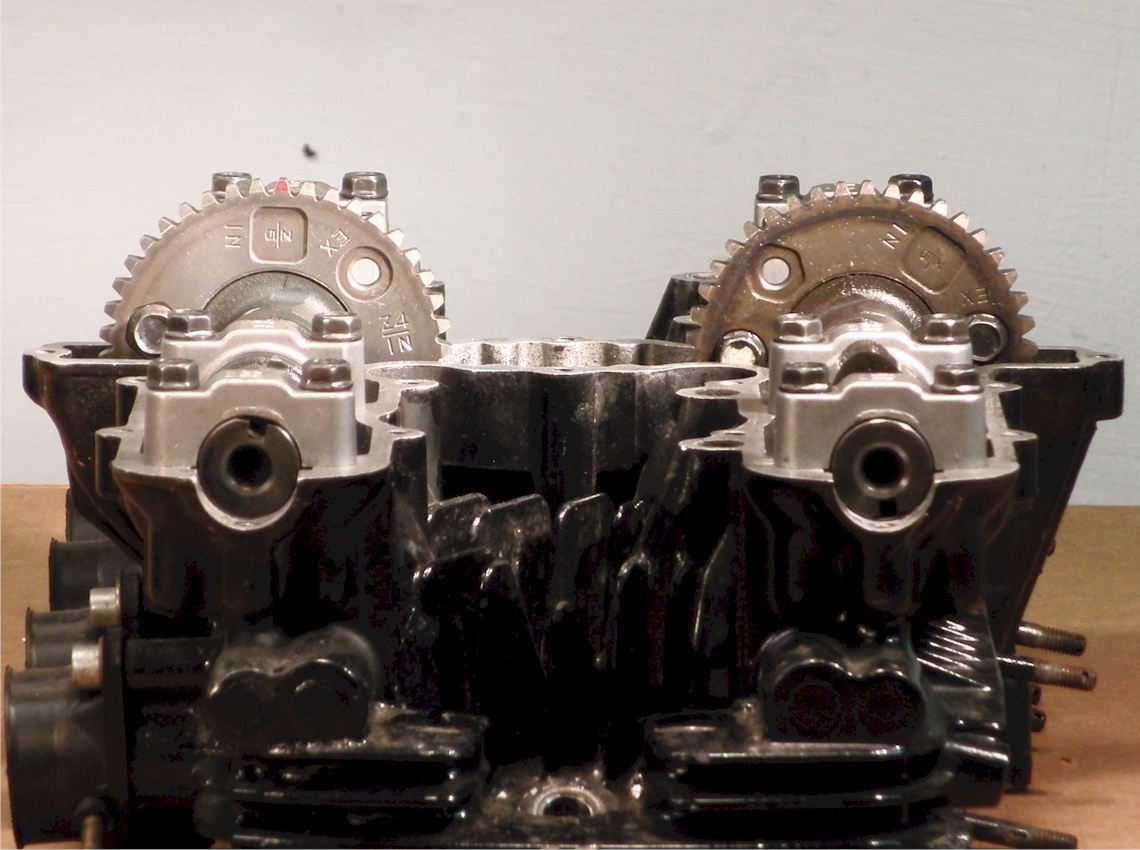
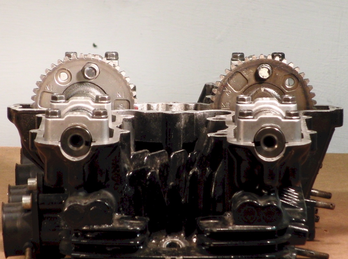
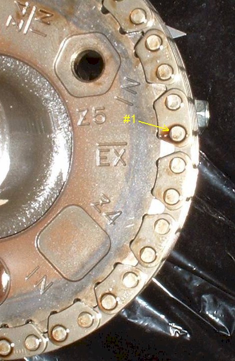
The intake camshaft is timed by counting the number of pins in the chain from the EX mark on the exhaust sprocket to the timing mark on the intake sprocket. Because the valve cover is part of the timing chain guide system, the final intake timing cannot be known with the valve cover off. In order to see the final intake timing, a valve cover with a window in it will be needed.
All motors will have the same pin count as in the following diagrams.
The Kz500 / Kz550 A,C,M,F & Kz550 D,H / Zr550 B motors use the
"Z/5" mark on the intake sprocket, as shown below.
The Kz400 J / Zx550 A motors use the
"Z4/IN" mark on the intake sprocket, as shown below.
The TDC mark is the line next to the letter "T" on the advancer.
With cyl #1 at TDC of the power stroke, measure the lash on intakes #1 and #3.
It will be tempting to measure the lash on other cylinders, since they will be obviously resting in a position which would allow for a feeler gauge to slip in. However, a careful analysis of the Kawasaki FSM procedure shows that Kawasaki deliberately chose those crank positions, and valve pairs, so that a lash would only be measured if the adjacent valve was slightly pressing on the valve. This would ensure that the camshaft was lightly pressed upward, thereby removing any slop in the measurement, making it very repeatable and consistent.
To make sure a particular cylinder is at the top of its power stroke, make sure its cam lobes are splayed outward, pointing away from each other.
It's best to rotate the engine forward only. That is the same rotation as the wheels of the bike moving forward. It may be helpful to put a hand on the top chain run to keep tension on it. This will prevent the chain from jumping teeth and coming out of time.
Note: The timing marks for the earlier bikes do not correspond to the marks on newer bikes, so the manual for a particular bike should be followed, and not a manual for a different bike. For instance, the 550 uses an "EX" mark on the exhaust sprocket to indicate where the camshaft should be when cylinder #1 is at top dead center. The early 650's have an "EX" mark on the exhaust sprocket which indicates the position at which to measure the lash on the exhaust valves. The problem is that the "EX" mark on the 650 lines up when cylinder #2 and #3 are at TDC. So use a 550 manual to service a 550, and a 650 manual to service a 650, and make sure the manuals are appropriate for the year and specific model being serviced.
Another issue is what to set the gap at. Some argue that the gap should be set to the largest gap within the recommended range in order to increase the service interval btween adjustments. But that usually results in the valves making more noise. This is an indicator that the valves are hitting harder in the seats, and the cam lobes are hitting the buckets harder (or shims, if the shims are on top). If the manual is followed explicitly, it will likely state if/when an adjustment is necessary. That should be followed. At the very least, the target lash should be in the middle of the range.
All cams have lobes with approximately the same base circle: 1.100" ~ 1.105", probably closer to 1.100".
All cams have bearing journals with the same diameter: .865".
Note: all rotational measurements are specified in crankshaft degrees.
-- Standard Grind: Kz550A, Kz550C, Kz550M, and Kz550F --
Note: all rotational measurements are specified in crankshaft degrees.
-- First Performance Grind: Kz550D, Kz550H, and Zr550B --
Note: all rotational measurements are specified in crankshaft degrees.
-- Second Performance Grind: Zx550A --
Here are some photos showing how the cam duration was measured. The lift measurements were all taken as movement of the valve. The rotation measurements were measured in degrees on the camshaft sprocket and multiplied by 2 to get crankshaft degrees.
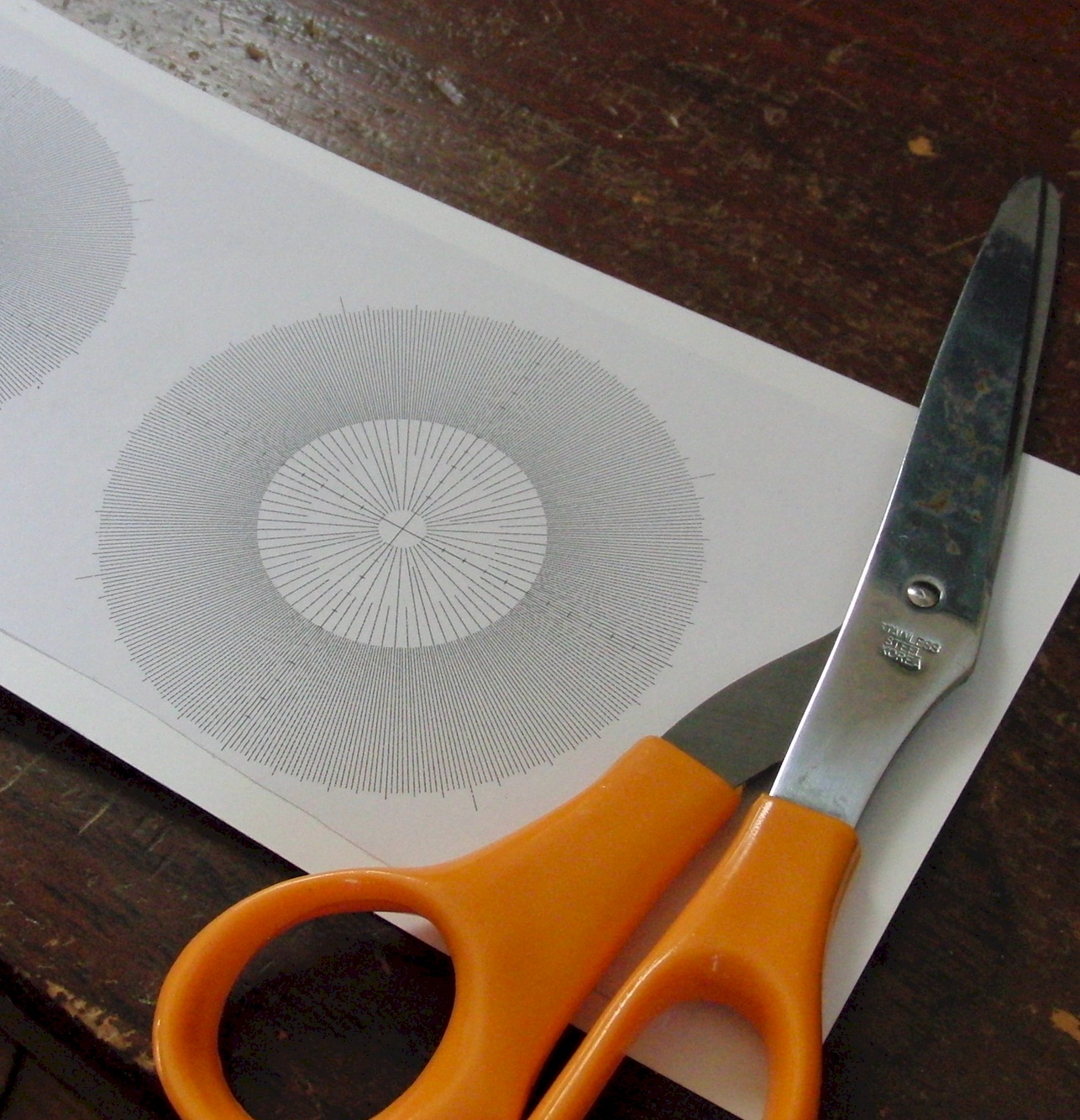
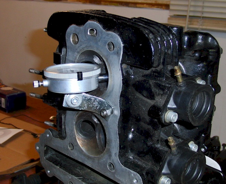
First, a degree wheel was glued to card stock, then cut out. The degree wheel can be downloaded and printed out from a link on the home page of this site.
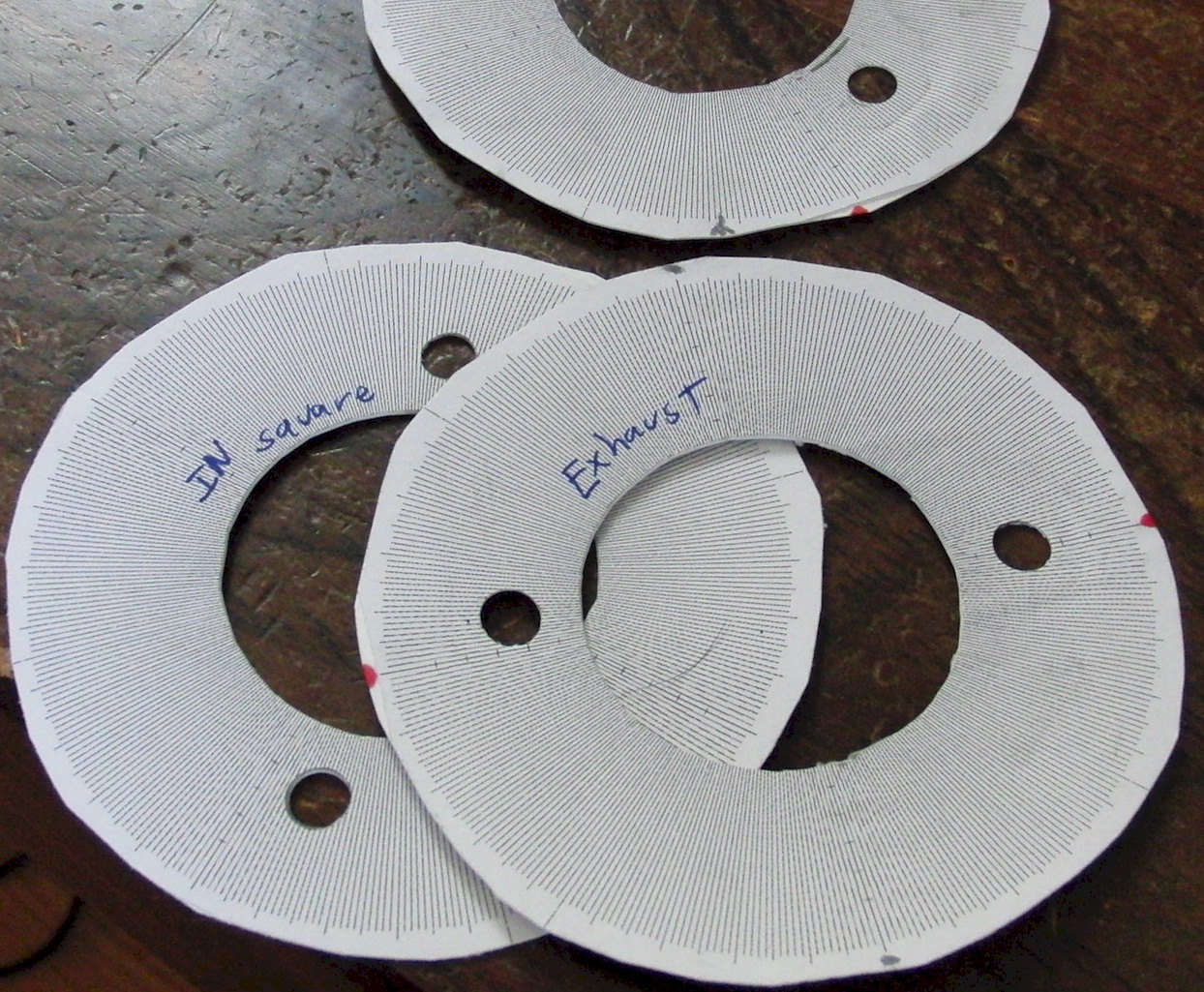
They were installed behind the sprocket, facing toward the cylinder under test, for convenience.
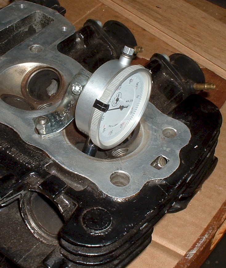
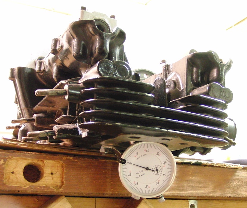
Next, a dial indicator was installed through the valve guide and bolted to the head.
Then a weak spring was put in place of a valve spring, and a push rod was installed in place of a valve.
Then the bucket was installed as normal.
This setup made the bucket ride on the cam lobe at all times. This means all readings were taken at zero lash. That is, no gap was present between the cam lobe and the bucket. Any change in cam lobe radius would translate directly to bucket (and thus, valve) movement.
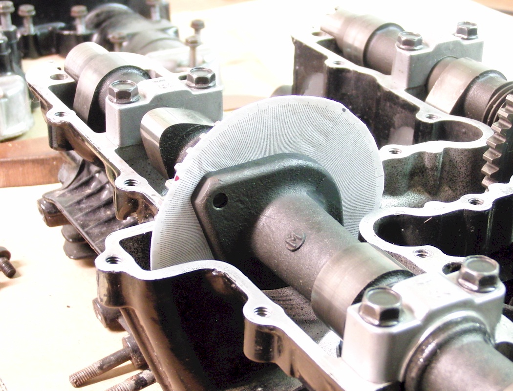
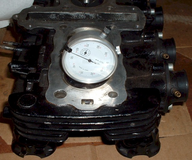
Here is the final assembly as it was during testing.
It is important to measure actual valve or bucket movement rather than just measuring the change in cam lobe radius. This is because the contact point of the cam lobe changes on the bucket as the bucket and cam move. This changes the reading. Cam lobe radius and valve travel are not a 1:1 relationship.
The degree wheel can be downloaded and printed out from a link on the home page of this site.
Once the camshafts are set in the proper orientation, and the #1 piston is still at TDC, the exact timing requires the line just above the "EX" mark to line up with the surface of the head where the valve cover gasket will sit. There should be no slack on the timing chain in the front of the motor. The mark will only line up when the exhaust camshaft is fully installed. The mark may be slightly higher than the head surface if the chain has stretched from wear, but only slightly. It should not be below the surface. Here is the EX mark on the sprocket with chain pin #1 pointed out for use when counting pins to the intake cam.
The motor case will have a line cast into it to align with the T marker line.
The 550's with electronic ignition use the advancer marked "1016".
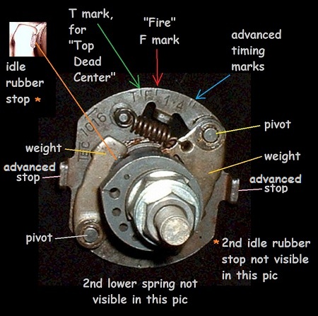
Image courtesy of "Patton" on Kzrider.com
With cyl #2 at TDC of the power stroke, measure the lash on exhaust #2 and #4.
With cyl #3 at TDC of the power stroke, measure the lash on exhaust #1 and #3.
With cyl #4 at TDC of the power stroke, measure the lash on intakes #2 and #4.
This can't be measured directly on any 550 cams (although, almost possible on the standard grind) because the lobe actually occupies more than half of the rotation of the cam. Because of this, there is no base circle that can be directly measured as a diameter. The base circle is the difference of the total cam height, measuring from the heel to toe of the cam, then subtracting the lobe lift value. The lobe lift value can be off slightly if due to machining tolerances, the valve axis does not exactly intersect the camshaft axis, or if the two axes are not exactly perpendicular, etc. So it is not clear how precise these values are for base circle.
Service limit is .863".
All use the same cam profile for intake and exhaust.
The Kz550A and Kz550C have a tachometer gear on the exhaust camshaft, which is the only difference.
These camshafts have part number 12044-1003.
If the exhaust camshaft has a tach gear, the part number is 12044-1004.
(For some reason, Kawasaki does not list a part number for the 80/81 A1/A2 intake cam, but they should be the same as A3 and A4.)
Kawasaki specifies the following timing:
The intake opens at 20 deg BTDC.
The intake closes at 48 deg ABDC.
The exhaust opens at 48 deg BBDC.
The exhaust closes at 20 deg ATDC.
From this, we see:
Intake is centered 104 deg ATDC.
Exhaust is centered 104 deg BTDC.
Duration is 248 deg.
Actual measurements on several cams yielded these values:
(See below for details on how the values were measured.)
The cam height measures about 1.400".
The cam height service limit is 1.3957"
The cam lobe-lift is .290"~.300".
Intake is centered 102 deg ATDC.
Exhaust is centered 104 deg BTDC.
The cam timing is specified at 0.3 mm (.012") lift with zero lash.
At ~.0002" lift, the duration is 362 deg.
At .006" lift, the duration is 302 deg.
At .012" lift, the duration is 248 deg.
At .040" lift, the duration is 210 deg.
At .050" lift, the duration is 204 deg.
All use the same cam profile for intake and exhaust.
The Kz550D has a tachometer gear on the exhaust camshaft, which is the only difference.
These camshafts have part number 12044-1034.
If the exhaust camshaft has a tach gear, the part number is 12044-1035.
The Kz550D and Kz550H use the same valves and valve train components except for cam-chain tensioner.
Kawasaki specifies the following timing:
The intake opens at 31 deg BTDC.
The intake closes at 59 deg ABDC.
The exhaust opens at 59 deg BBDC.
The exhaust closes at 31 deg ATDC.
From this, we see:
Intake is centered 104 deg ATDC.
Exhaust is centered 104 deg BTDC.
Duration is 270 deg.
Actual measurements on several cams yielded these values:
(See below for details on how the values were measured.)
The cam height measures about 1.428".
The cam lobe-lift is .320"~.330".
Intake is centered 102 deg ATDC.
Exhaust is centered 102 deg BTDC.
The cam timing is specified at 0.3 mm (.012") lift with zero lash.
At ~.0002" lift, the duration is 385 deg.
At .006" lift, the duration is 324 deg.
At .012" lift, the duration is 268 deg.
At .040" lift, the duration is 232 deg.
At .050" lift, the duration is 227 deg.
This bike uses the same camshaft for intake and exhaust, but the intake timing is offset from the exhaust by the use of a unique intake sprocket.
These camshafts have part number 12044-1059.
Even though the cams are the same, for assembly purposes, it appears the factory put a red paint mark on the camshaft designated for exhaust duty, and a yellow or white paint mark on the camshaft designated for intake duty.
Kawasaki specifies the following timing:
The intake opens at 46 deg BTDC.
The intake closes at 54 deg ABDC.
The exhaust opens at 64 deg BBDC.
The exhaust closes at 36 deg ATDC.
From this, we see:
Intake timing is centered 94 deg ATDC.
Exhaust timing is centered 104 deg BTDC.
Duration is 280 deg.
Intake cam is 10 deg advanced relative to the exhaust cam. (The change is only 5 degrees on the sprocket. Double that gives 10 degrees of crank rotation.)
Actual measurements on several cams yielded these values:
(See below for details on how the values were measured.)
The cam height measures about 1.429".
The cam lobe-lift is .320"~.330".
Intake is centered 95 deg ATDC.
Exhaust is centered 103 deg BTDC.
The cam timing is specified at 0.3 mm (.012") lift with zero lash.
At ~.0002" lift, the duration is 394 deg.
At .006" lift, the duration is 333 deg.
At .012" lift, the duration is 272 deg. (This result is lower than Kawasaki published value.)
At .040" lift, the duration is 239 deg.
At .050" lift, the duration is 234 deg.
Here are the specs quoted by Megacycle.
They pretty much agree with measurements for the Kz550 A, C, M, F (outlined in green)
and Kz550 D, H & Zr550 B (outlined in red). All of the Megacycle cams listed here have lobe centers aligned with the timing centers, so it is assumed the cams are symmetrical (closing profile is a mirror of the opening profile on the cam lobe).
KZ550A (standard), KZ550C (chainLTD), KZ550M (shaftLTD), KZ550F (Spectre/shaftLTD), and ZR550B (Zephyr) are specified to have 9.5:1 compression and use piston part number 13001-1121. (The Zr550A known as the Z550F also has 9.5 compression.)
The Kz550A1/A2, and C1/C2, don't actually have a part number listed for the standard size piston, but do list the double over-size LL piston which is 1.00 mm (.040") over size, and has part number 13027-1053. That same part number is also used on the Kz550A3,A4,C3,C4,F1,F2, and M1, along with the Zr550B1-B4. So it is assumed the A1/A2 and C1/C2 use standard piston 13001-1121 as well.
The ZX550A motor is specified to have 10:1 compression and uses piston part number 13001-1166.
All of the 550 motors mentioned use the same crankshaft (13031-1014).
All of the 550 motors mentioned use the same connecting rods (13251-1004-JJ), but the ZR550B uses a supersede part number 13251-1004-EE.
The Kz550D Gpz, the Kz550H Gpz, the Zx550A Gpz, and the Zr550B Zephyr all have engine case numbers starting with "KZ550DE".
KZ550 A3/A4, C3/C4, M, F, D, and H all have the same valves, as do the ZX550A and ZR550B.
KZ550 A1/A2 and C1/C2 have different part numbers listed for valves.
All of the 550 motors, (along with the 650, 750 and many more) use the same buckets (12032-1001) which are nominally 33mm OD. I actually measured 1.2980 inch OD on a couple examples, near the middle, and at 90 degree apart diameters.